Cryogenic Rubotherm IsoSORP
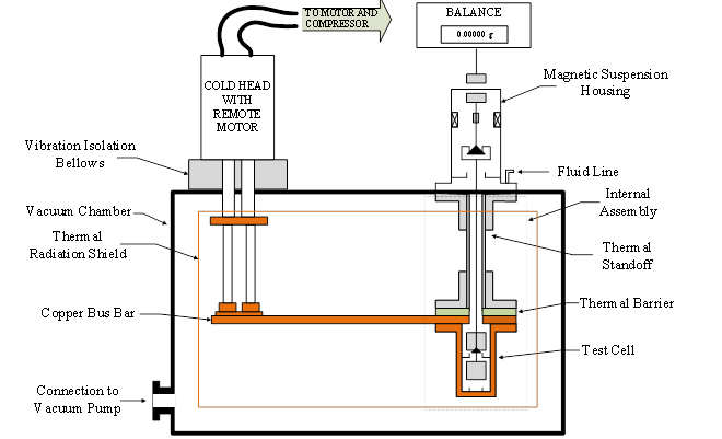
Rubotherm IsoSORP instruments utilize a Magnetic Suspension Balance to provide highly accurate fluid density and sorption measurements. The system utilizes Archimedes’ principle to determine fluid density by suspending a sinker of known mass and volume in a fluid and measuring the weight with a precision balance. The applied force is transmitted to the balance by the magnetic suspension which decouples the testing fluid from the balance. The Rubotherm IsoSORP at Washington State University has recently been retrofitted for cryogenic temperatures and pressure up to 4000 psi. By placing the test cell in a vacuum chamber and thermally connecting it to a Cryomech cryocooler I have been able to achieve temperatures down to 15 K. A system diagram is provided in Figure 1 showing the key components. Sorption measurements can be conducted by replacing the bottom sinker with a weighing basket filled with the sorption material and measuring the change in mass. The system is currently set up to conduct density measurements with a single quartz sinker.
The system’s operation and accuracy has been validated by conducting initial density measurements of liquid nitrogen and liquid hydrogen. Initial liquid nitrogen density measurements conducted from 79.6 K to 83.7 K had a maximum deviation of 0.08% from the equation of state. Liquid parahydrogen density measurements were conducted from 15 K to 31 K at pressures up to 625 psi with a maximum deviation of 0.1% from the equation of state.
The Rubotherm system at WSU is capable of conducting pure fluid density and sorption measurements from 15 K to 293 K at pressure up to 4000 psi. We are in the process of modifying the system to have the ability to conduct mixture measurement using mass spectroscopy to determine fluid composition. The current system configuration is not intended for low density gaseous measurements.