Cubic Cryogenic Chamber
 The first cryostat of the lab, the Cubic Cryo Chamber (CCC) was inspired by modular cryostat designs in the Pellet Fueling of Fusion Plasmas group at Oak Ridge National Laboratory. The general utility of CCC is awesome, as exemplified by the diversity of experiments it has completed over the years.
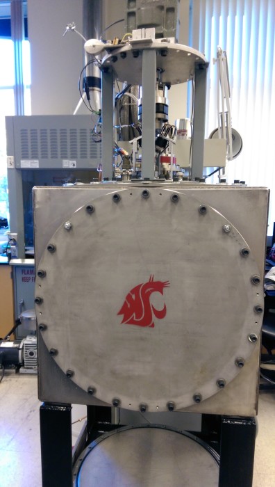
C3 is a steel vacuum chamber designed to be easily configurable for cryogenic experiments. The chamber itself is a cube shape comprised of 6 square, 26 inch, steel walls (~17500 in3) with a hole in each to allow access from any side as well as customization for future experiments. Circular steel coverings are made for each individual hole and can be customized with extra holes to adapt to any experimental needs. We can design and machine these to serve our individual purposes, such as including viewing ports for optical information, or holes to serve as ports for our vacuum pump, cryocooler, and various other needed components. Currently 4 of the 6 plates are whole and only act as coverings. The plate on one side has a hole where the vacuum pump systems hook into the chamber. The plate on top has two holes, one for mounting the cryocooler, and one for wiring and fluid passthroughs.
Table of Contents
Relevant Links
Cryogenic Hydrogen Embrittlement
Specifications
Test Facility Equipment:
- Vacuum Chamber
- 17500 in3 in volume
- Customizable entry/exit ports through any of the 6 walls
- Leybold TRIVAC D 8 A Roughing pump (~10-1 Pa)
- Agilent Turbo-V 81 M Turbomolecular Pump (~10-5 Pa)
- Cryomech CP 1010 Helium Compressor/PT415 Cryocooler
- 40W @ 45K
- 5W @4.2K
- 2.8K base temperature
- Lakeshore 336 Temperature Controller
- 2 heater power outputs
- 4 temperature sensor inputs
Thermodynamic State Point Delivery:
- Maximum Temperature (cryocooler off)……………………..~310 K
- Maximum Temperature (cryocooler on – w/o MLI blanket and w/ thermal resistor insert): ~220 K
- Minimum Temperature (cryocooler on – w/o MLI blanket and w/ thermal resistor insert): ~25 K
- Minimum Temperature (cryocooler on – w/ MLI blanket and w/o thermal resistor insert): ~5 K
- Maximum (tested) Inlet Pressure……………………………..~ 20 psig
- Minimum Inlet Pressure……………………………………..near vacuum
- Inlet Fluid Phase Type………………………………………….vapor, liquid
- Testing Fluid……………………………………………………………….. H2, He
- Processed hydrogen/helium purity: 99.999%
Test Specimen Dimensions:
- Diameter: …………………………………….4.73 in
- Thickness Range: ……………..0.001 – 0.05 in
Instrument/Measurement Specifications:
- Test Cycle Time (cryocooler on): ~ 6 hours per measurement
- Leak Rate/Mass Spectrometry Measurement Method: ASM Graph D+ Leak Detector
- Leak Rate/Mass Spectrometry Measurement Range (for He): 3 * 10-10 to 1 * 100 mbar – l / sec
- Leak Rate/Mass Spectrometry Measurement Uncertainty: ± 10 %
- Temperature Measurement Method: Lakeshore PT-111-14L (i.e. platinum RTDs)
- Temperature Measurement Uncertainty: ± 0.024 K
- Pressure Measurement Method: Keller American Valueline (100 psig)
- Pressure Measurement Uncertainty: ± 0.25 psig
![]()
2016-2020: Kjell Westra and Helium Permeation Through Thin Polymer Films
Utilizing polymers as a tank material for the storage of cryogenic propellants in spacecraft provides several advantages over traditional metals. Not only is the former lighter, but the interaction of polymers with cosmic radiation produces less secondary radiation that could harm astronauts. Concerns still remain though: permeation of propellant through the polymer must be minimal (a tank is no good if the contained liquid leaks right through the tank wall).
To determine if the helium permeability of polymers is significant at cryogenic temperatures, we designed and built a test cell to house thin polymer samples between 0.001 – 0.050 inches thick. The top and bottom faces of the sample are subjected to 35 psi of helium and vacuum, respectively, and the resulting pressure gradient drives the permeation of helium through the sample, the rate of which is tracked by an ASDM Graph D+ leak detector. The temperature of the test cell (and any ongoing permeation test) can be modulated between 20 – 200 K using a PT-415 cryocooler and close-loop PID controlled heaters.
The permeabilities of polyethylene terephthalate (PET), polyetheretherketone (PEEK), and polyetherimide (PEI) to helium have been characterized between room temperature and 20 K. Below 100, permeation rates fell below the sensitivity limit of the leak detector, suggesting that these polymers are sufficiently impermeable to helium for use as tank materials.
Research Highlights:
Project Sponsors:
National Aeronautics and Space Administration (NASA)
Joint Center for Aerospace and Technology Innovation (JCATI)
Blue Origin
![]()
2010-2015: Jacob Fisher and Solid Hydrogen Twin Screw Extruder
A prototype hydrogenic twin screw extruder has demonstrated the feasibility of producing fuel for fusion tokamaks however for it to be used on the ITER tokamak it will have to produce 0.33 g/s throughput at 99.9% reliability. Throughput instability and unknown scaling factors of the prototype extruder has prompted the design and construction of the Diagnostic Twin Screw Extruder (DTSE) to measure fundamental parameters and develop a predictive throughput model to insure the next generation extruders can meet ITER requirements. The ITER tokamak is an experimental reactor being built to exhibit fusion technology needed for commercial power plants. Fusion power plants have the potential to meet the future world energy demand without producing green house gases or long lived radioactive waste.

Hydrogenic twin screw extruder operation has been modeled previously by Dr. Jacob Leachman using numerical heat transfer methods to predict the temperature distribution. This model assumed a throughput efficiency of 100% meaning backflow was not taken into account. Backflow or leakage flow has been identified as a major proponent of throughput instabilities and reduces extruder throughput to zero in some cases. Backflow in twin screw extruders has been modeled in polymer literature with work done by L.P.B.M. Janssen who indicated four clearance gaps as areas of leakage flow. However the equations developed for flow through these gaps do not directly translate to hydrogenic material because polymer melts have different flow properties. Rheology studies on hydrogenic material have been done by J.W. Leachman which produced the temperature and shear rate dependence of shear stress; a thermophysical property needed for heat transfer and fluid flow modeling. The literature on hydrogenic twin screw extrusion is short: only two twin screw extruders have been built at Oak Ridge National Lab to experiment with producing solid hydrogenic material. Neither device was instrumented to record screw temperature distributions need for model validation.

A finite volume numerical model combining heat and mass transfer has been developed to predict the throughput of hydrogenic twin screw extruders. The model expands Leachman’s temperature distribution model to include a mass balance therefore incorporating temperature and leakage flow effects on throughput. The leakage flow equations from Janssen are used in the mass balance and have been modified to better emulate hydrogenic fluid properties based on experimental results from the DTSE and other references. The model can be used to produce plots that compare extruder throughput to screw speed and required cooling power for different extruder geometry. These results can be used by fusion scientists to size and operate twin screw extruders to fuel fusion tokamaks like ITER.

The throughput model will be validated by data taken from experiments on the specifically designed and built Diagnostic Twin Screw Extruder. The DTSE is cooled by a cryogenic refrigerator using a special helium refrigeration cycle to cool the DTSE to -448 °F (6 K). The DTSE is suspended in a custom modular vacuum chamber to eliminate convection heat transfer. Thermal radiation is also eliminated using a special made multi layer insulation blanket wrapped around a copper radiation shield that is actively cooled by the cryogenic refrigerator. Temperature sensors are embedded in the screw threads of both screws to provide the most accurate extrudate temperature measurements of any hydrogenic twin screw extruder. The DTSE also has sensors to monitor torque, speed, and mass flow rate during testing. The DTSE operates by condensing gas to a solid from an external reservoir. A DC motor powers the screws which convey the solid through a barrel and out a nozzle where it melts and the liquid follows a circulation loop back to the top of the extruder. The benefit of a closed loop system is that when a test is complete the solid changes phase back to a gas and returns to the reservoir reducing cost and required cooling over a once-through system.
Thus far the DTSE has extruded solid nitrogen and neon producing torque, speed, and temperature measurements. Preliminary analysis suggests higher temperatures in the intermeshing zone than in the screw channels. If the temperature in the intermeshing zone exceeds the extrudate melting temperature then high leakage flow through the calendaring gap would occur. This helps guide throughput model development by adjusting fluid properties in specific backflow equations. Initial measurements also showed change in extrudate temperature along the barrel being only 2 K suggesting higher heat transfer than predicted. Further tests are being conducted on neon, deuterium, and hydrogen with the goal of collecting data over a wide extruder operating range. The data will improve the accuracy of the throughput model and allow it to predict deuterium-tritium extrudate, the fuel to be used in the ITER tokamak.