The safety systems in place at HYPER are based off of the DOE (Department of Energy) Hydrogen Safety Panel’s
Safety Planning for Hydrogen and Fuel Cell Projects – March 2016. The safety plan outline below is based around the safety plan outline in this document. To efficiently develop a full safety plan, you should begin this process when a design has completed a preliminary design review or when the design is about 33% complete and the key components and how they’re connected are defined.
Safety Plan Outline
- Scope of Work
- Organizational Safety Information
- Project Safety
- Communication Plan
- Other Comments or Concerns
1) Scope of Work
Also known as system definition. We’re defining the purpose, goals, and objectives of an activity. Then, we define the equipment, tools, pieces, and people involved with the activity and how it will be used. A simple picture or sketch of these key things can be the most efficient way to show these things and how they’re connected. We ultimately need the same block system diagram as in the preliminary hazard analysis. The important part is to clearly define boundaries of the system in question and scope of work.
2) Organizational Safety Information
3) Project Safety
A step-by-step analysis of how to identify safety vulnerabilities (HAZOP), how to mitigate those safety vulnerabilities through careful operating procedures, how to respond to potential failures (FMEA), and how to analyze and correct if failures do occur (Fault Tree Analysis, Management of Change).
For an example of a safety plan in place at HYPER, see
WSU CHEF Safety Plan – 2020.
HAZOP (Hazard and Operability Analysis)
The steps for completing a HAZOP are very similar to the preliminary hazard analysis you completed above, just much more comprehensive.
Step 1: Create Block Flow System Diagrams and Other Supporting Documents
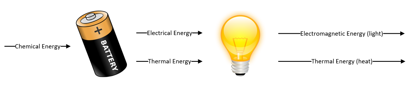
The flow of the block should follow the primary energy vector from start to finish (eg. the hydrogen is delivered, processed, and vented to the atmosphere). Each block is numbered and becomes a topic of the HAZOP. Ideally, the system is as fully designed as possible with a Block System Diagram (see example below), Plumbing and Instrumentation Diagram (P&ID) (see examples below), a Bill of Materials (see example:
MHGU BILL OF MATERIALS 7-10-2020), and any other system layout drawings (bring these documents and lists with you to the HAZOP meeting). The more detail you can provide up front, the more robust your HAZOP will be.
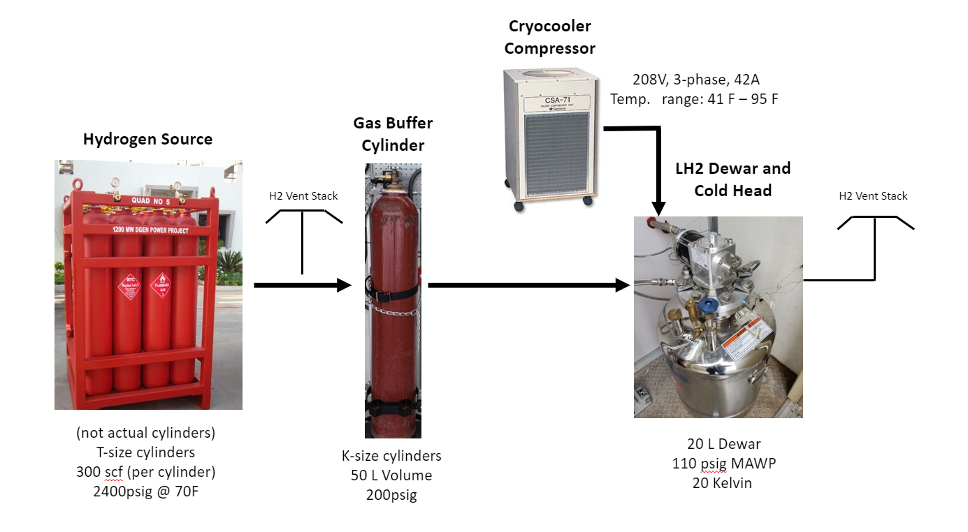
HYPER Example Block System Diagram (from MHGU project):
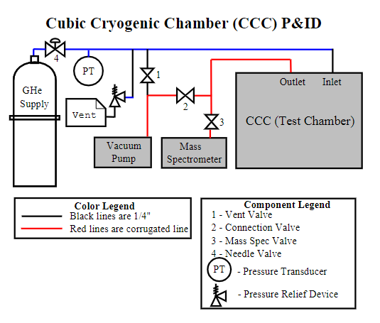
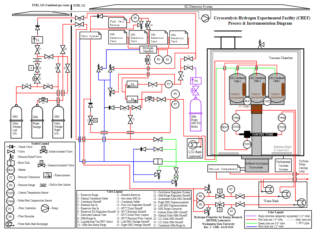
HYPER Example P&IDs:
Step 2: Define Guide Words
For each block, the following guide words are applied to identify potential hazards for a system. The guide words are potential unwanted outcomes. Some example guide words we commonly use at HYPER include:
- High flow / Low/no flow
- High level / Low level
- High pressure / Low pressure
- High temperature / Low temperature
- High concentration / Low concentration
- High power / Low power
- Reverse / misdirected flow
- Leak / Rupture
- No movement / Unintended movement
- Break
This guidewords list is by no means comprehensive. You need to evaluate potential ways that the energy in your system could deviate from nominal operation. This includes passive safety controls as they are only less susceptible to guide word deviations.
Step 3: Perform HAZOP
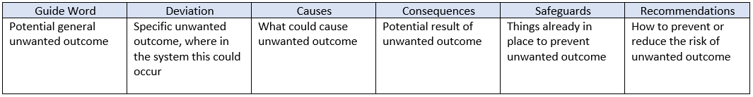
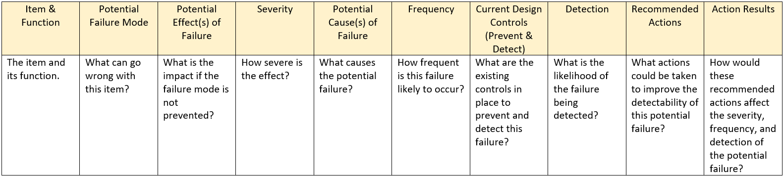
For each block or node, each of the guide words above becomes a row or rows in the following table. Make sure not to skip a guide word.
This can take a while! For a typical block or node in a HYPER system, we estimate about 3 hours which is about a week or two for an entire system. For an example of a HAZOP performed at HYPER, see
HAZOP VCS Tank. When performing a HAZOP, assemble a team, assign roles (HAZOP lead, HAZOP veteran, note taker, document visual lead, and time keeper), and meet in a place where you can really focus and sustain the energy. Here are some example HYPER HAZOP guidelines and expectations:
- All team members have an equal say
- Any concern, no matter how inconsequential it appears, is fair to suggest
- All team members are expected to contribute
- Spin off questions derived from a deviation or what-if question will be given a priority before moving on
- Criticism of questions or ideas is not allowed
- The focus is to identify hazards, solutions can be discussed later
- Please refrain from emailing and texting, we will take breaks.
Always remember that your system operates within the bigger system of the university or a campus building. Deviations to these overarching systems can influence the assumptions that your HAZOP is predicated upon. Hence, lab members should sign up for WSU myFacilities event notifications. This will alert teams members to potential service disruptions such as those affecting power and HVAC. Lab members should also sign up for WSU Alerts.
If you can’t fully mitigate the issue in the HAZOP (if you have deviations with no recommendations), this will become part of the FMEA (Failure Modes & Effects Analysis) in a later section. But first, we need to carefully list all of the operating procedures to ensure they comply and conform with the HAZOP.
Operating Procedures
If a multi-step process is going to be repeated in the future by anyone, it should be developed as a written procedure. Good procedures are part of our
6s system at HYPER. The 6s’ include: sort, systemize, sweep, standardize, sustain, safety. As WSU’s assistant director for environmental health and safety, Shawn Ringo, says, “Poor housekeeping contributes significantly to injury frequencies, and as frequencies increase, so does the potential for more severe injury.” Example procedures could include:
- Make sure the area is sorted, systemized, and swept prior to starting
- Operation Readiness Inspection (ORI) and safety system testing
- Purging the system
- System startup
- Data sampling
- System shutdown
- System passivation for safe storage
See
MHGU LH2 Transfer Standard Operating Procedure for an example checklist used in HYPER. These should be simple and easy to understand by someone unfamiliar with the experiment including freshman and fire fighter/first responders.
After all operating procedures are developed and comply and conform with the HAZOP, the next step is to complete an FMEA based around the issues that could not be fully mitigated in the HAZOP.
FMEA (Failure Modes & Effects Analysis)
The important thing to understand when completing an FMEA is that it works in conjuncture with the HAZOP. HAZOPs help you identify and minimize hazards. However, not all hazards can be totally mitigated and the potential for failure, despite our best engineering, always exists. The Failure Modes & Effects Analysis matrix considers those potential failure modes and how they will affect other systems and what maintenance and detection processes should be in place. FMEA is a process that allows you to identify potential failures. According to the
Safety Planning for Hydrogen and Fuel Cell Projects – March 2016, the FMEA process is meant to identify
top level hazards and events. These are only the most severe, catastrophic events that a system could have. This information can be used for the Site Emergency Response Plan.
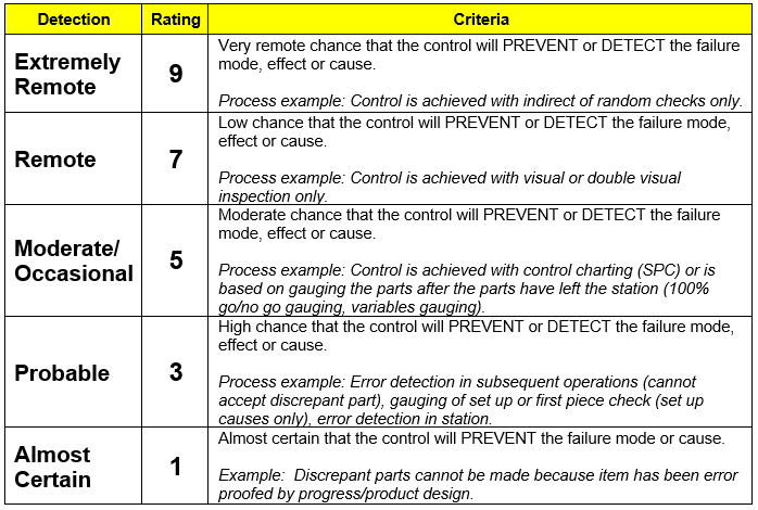
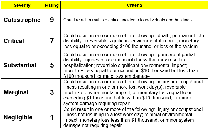
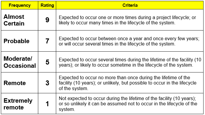
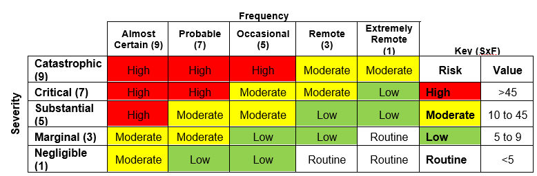
See the tables in the How to Begin a Safety Analysis section for severity and frequency. See the table below for how to quantify detectability.
 Example
Below is an example of an FMEA done at HYPER. This is a small part of a larger FMEA done by the H2Flo team.
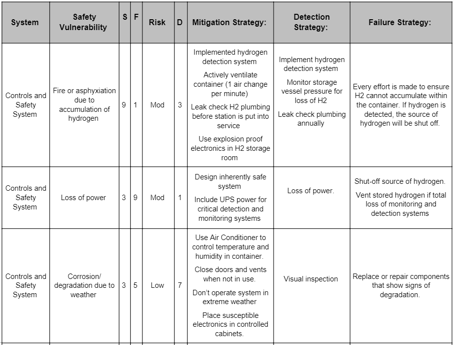
When a safety control failure contributes to unacceptable risk outcomes, the FMEA table should identify the need for redundant safety controls.
The FMEA provides a detailed approach to mitigating potential hazards in a system. Academia most often performs proof-of-concept experiments which require approaches like the HAZOP and FMEA method. In the case of a higher risk experiment or project, a more thorough approach can be taken in which the HAZOP and FMEA are performed in addition to a Fault Tree Analysis (FTA).
Fault Tree Analysis (FTA)
FTA is typically performed in two situations:
- Scenario 1: during the design phase typically for high consequence vehicles, systems, etc.
This is typically part of a system safety assessment and related activities to ensure adequate levels of safety are provided. In regulated industries, there are typically regulations and standards that define the type of analysis required. This type of FTA, while important, is outside the scope of this webpage.
- Scenario 2: after a near miss, incident, or accident has occurred and you want to understand causes of the specific event, or other combination of failures that can result in the unwanted outcome.
In this scenario, FTA is performed when a deviation has occurred from the nominal operation plan (an unwanted outcome (near miss, incident, etc.) has occurred). FTA can be qualitative only or qualitative and quantitative. Most of the research in HYPER is completed on prototype proof-of-concepts, meaning we often do not have enough data for a rigorous fault tree analysis. The following steps on how to construct a fault tree are inspired by and adapted from the course
Diagnosing Unwanted Outcomes™. This is a type of Root Cause Analysis (RCA) based on proven methods and tools such as Fault Tree Analysis and Failure Modes & Effects Analysis. Note that the creator of this course periodically offers heavily discounted courses for college engineering students.
The Fault Tree Analysis Process (supporting scenario 2 above)
:
- Define the system: quick summary of the deviation, block flow system diagram, list knowns, unknowns, and assumptions.
- Develop a fault tree: write the event sentence hierarchy (see the Diagnosing Unwanted Outcomes™ example below), draw the fault tree and apply the sentence hierarchy to the tree, rank in order the most likely contributors to the fault. (For current FTA experts: Diagnosing Unwanted Outcomes™ and similar RCA methods are revealing a single cut set of a larger fault tree. This is the cut set that occurred as part of the deviation).
- Provide recommendations and a monitoring plan before executing a management of change process.
For an example of how a Fault Tree analysis is performed using Diagnosing Unwanted Outcomes™, see
MHGU Unwanted Valve Opening Analysis.
Fault Tree Analysis is an effective way to either thoroughly identify potential hazards or to understand causes of a specific event (near miss, incident, accident). After identifying, analyzing, and mitigating potential hazards, there are often changes that need to be made to the experiment and overall safety plan. This is done through Management of Change.
Management of Change
When managing change to a system or project, it is helpful to have procedures in place to identify and make those changes. The following steps are an example of what we do here at HYPER and can be seen in the
CHEF Management of Change Procedures document. We’ll first discuss the process, then tools to help facilitate, and finally communicating management of change.
Management of Change Process:
- A need to change is identified that involves changing a procedure, operating set point, or part component layout.
- The change is discussed with at least two knowledgeable members of the lab to get second opinions on the necessity of the change. Details of what should be changed and how are discussed.
- A proposal for change is created, stating the need for change and details of what the change will include:
a. applicability and compliance with relevant engineering standards,
b. necessary sizing calculations,
c. details of implementation of the change, and
d. how the change affects this document, including HAZOP and FMEA matrix and operating procedures.
- The full proposal is discussed with the PI and experiment operators. If it is agreed upon the details of the change, the change is implemented, otherwise the change is discarded or is redesigned. The PI has the final decision on approval.
- Implement the changes. Document these changes (i.e. the proposal) for future reference. Communicate the implementation and completion of the changes with others in the lab through the proper lab Microsoft Teams channel.
- If procedures are affected by the change, update this document with new operating procedures. Detail any changes or updates to the document in the changelog at the end of the document.
- If new maintenance / safety concerns arise from the change, note them in the proper areas in this document.
Management of Change Tools:
The plumbing and instrumentation diagram used in the safety plan above is only part of the spectrum of components used by a system. We have these additional tools to manage part numbering and change. See the
MHGU BILL OF MATERIALS 7-10-2020 for the system that H2Flo uses. To learn more about the Bill of Materials, see
How to Procure Parts Easily and Efficiently – The HYPER Way.
Communicating Management of Change:
The above change tools and procedure automatically updates the most current safety plan in the experiment’s Microsoft Teams channel. However, you should post a note to the channel notifying everyone of the change.
Even seasoned experimentalists can be caught off guard by an assistant making changes and not properly notifying everyone. Management of change procedures are important to take into account when constructing a lab safety plan. If a change slips through the cracks or fails to work as intended, it is important to be prepared with emergency response plans and procedures.
Emergency Response
What exactly is an emergency and how do you respond to one? There is no exact definition that can prepare you for an emergency situation. Generally, if you’re concerned about severe damage to people and/or equipment, that is considered an emergency. Proper training and continually improving judgement and discretion can help prepare you for emergencies and how to respond to them.
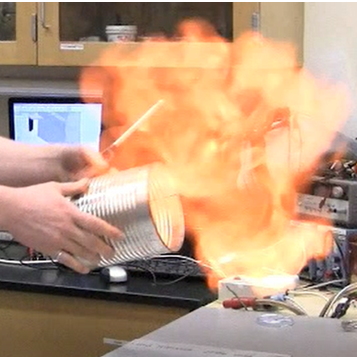
With cryogenic hydrogen, everything should go as planned. However, with complex systems, it’s impossible to plan for everything. Our
near miss in 2016 was a close call but the judgement and discretions applied in the situation prevented an incident. Below are the emergency response steps in place at HYPER.
HYPER Emergency Response Steps:
- Follow the system safety plan shut down procedure (note that all of our systems are designed to safe themselves if left alone, however this is only a last resort).
- Should deviations occur from the system safety plan shut down procedure, call the PI (Jake) and exercise judgement and discretion to manually safe the system (also empower others to use their own judgement and discretion).
- If an emergency or incident is unavoidable, refer to the emergency site response plan and follow the steps to communicate and notify relevant authorities. Call 911 whenever additional assistance could mitigate damage to people or property. It is a free resource.
For an example of an emergency response plan in place at HYPER within the H2Flo team, see
HYPER Emergency Plan 001 – Hydrogen Research Station.
Note: any safety plan should include Material Safety Data Sheets (MSDS) for all chemicals in or around the experiment. This should conclude the safety plan.


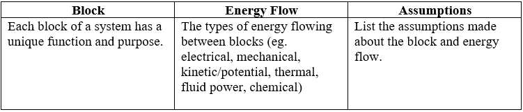
 Completing the following table will allow you to compile and expand on the information in your block system diagram drawing.
 Since academia typically performs proof-of-concept experiments with untrained operators, all of our projects need to be in the routine to low risk category. This safety planning process is designed to help people determine whether their risk is low or routine. If not, the full safety plan process is designed to take moderate to high risks and engineer safety systems to make them low or routine. For example, 208 volt power supply would be easily moderate to high risk if done for the first time in human history. But with careful planning and error proofing, plugging in this type of cable is now low or routine risk.