A Journey
Background
 I had always enjoyed learning. Taking things apart, seeing how they worked, discovering the purpose of each individual part. I was always sketching out ideas for inventions and writing stories around them. I was fascinated by the flow of technology: how every technology built off its predecessors from prehistoric times to the modern-day. This let me understand why a tool was built like it was. I also spent considerable time with creative writing, usually taking place sometime in the past with the plot revolving around advancing technology of the day.
My father was a mechanical engineer, so he was able to teach me the basics of mathematics and how to apply it. This inspired me to become an engineer as well. He made his career in HVAC systems and energy conservation. Though he attained fulfillment from it, I knew I wanted something different.
In choosing a university I made my first of many “self-improvements.” I had done exceedingly well in high school, academically. But I avoided social contact and tended to keep to myself, to the point that unexpected conversations were difficult. Unfortunately, being an engineer would involve “teams” and “other people.” Work done as an engineer would be worthless if I couldn’t explain it to someone else. It eventually came down to UW (University of Washington) or WSU (Washington State University). I grew up in the Seattle area, so UW was closer to home, and many people from my high school went here. But I knew that if I went to UW, I could get by with the friends I already made in high school. I would have little need to step outside my comfort zone. So instead, I chose WSU to force myself to become sociable.
But my first two years in college were a drag. I slogged through the basics of chemistry and humanities and calculus. At least, I knew I made the right choice in not choosing chemical engineering. The lab course on how materials break was a breath of fresh air. I was finally learning something that was not only exciting but immediately applicable. Thermodynamics, too, was especially interesting. I finally got to understand how engines and refrigerators worked, something I had been curious about for a long time.
Table of Contents
This page summarizes some of my accomplishments, written in the form of a story. If you prefer them listed in bullet points, check it out here:
Gregory Wallace
Compressor Sizing
I met Jake Leachman in my Junior year, back in August of 2015. I was taking his class on engineering systems, a junior-level design class for preparing us for Senior Design. The project was a hydrogen refueling station for vehicles. The overall design used a novel method to compress hydrogen to the necessary pressures for storage using a liquefaction cycle. The class was split up into teams, each of which would refine the design of one subsystem. My system was Hydrogen Compression with the primary goal of scoping out a compressor to fit the system’s needs.
I could finally apply what I had learned in class to a real-world problem that I cared about. Hydrogen vehicles had been a previous interest of mine, but the last two years of drudgery had temporarily sapped my creative spirit. So, we set about determining the requirements of our system and learning about the specifics of hydrogen and compressors.
My role on the team was liaison: I communicated between the various teams and with the leadership (grad students and Jake). But the needs of the leadership and other groups were varied and inconsistent: did we need 200psi or 1500psi outlet pressure? Do we need a flow rate of 15kg/hr or do we only need 3kg/hr? The reason should have been obvious: the system wasn’t fully planned out yet. If they had developed with that much detail, they wouldn’t have needed us to do design work. Though I didn’t fully realize it at the time, this was something college hadn’t prepared me for. Most college problems (at least in 1st and 2nd year) came with all the necessary information to rout to a single, exact answer. But real-life problems worth solving are never so clear. Solutions are rarely single number, but ranges of possibilities with the consideration of “is this realistic?”
We combed through catalogs and manufacturer websites while contacting distributors for pricing estimates. We followed through with a few leads from RIX and Hydro-Pac, but ultimately concluded there wasn’t a commercial sold compressor that fit our needs (and was within a reasonable budget). We also noticed the lack of technical details on many websites and catalogs. They usually provided maximum pressure output and maximum flow rate, but rarely provided a curve of the performance between those two options (obviously it would not output max flow rate at max pressure).
The liaisons also managed the class’ website, including pages for each team. I wrote the Compression team’s page, which can be seen here:
https://hub.wsu.edu/ise/design/compressor/
A club, Innovations for Sustainable Energy (ISE), was created to continue work on the Refueling Station.
Gas Booster Restoration
In light of the difficulties in finding a proper compressor, Jake suggested another option, at least for testing the overall system on the smaller scale. We had access to two gas boosters that could manage hydrogen. But nobody in our lab was familiar with how they worked. We didn’t even know if they were in working order. So, I took up the challenge of renovating them.
Now is a good time to note that this took place in the summer and fall (2016). Chronologically, this occurred after my senior-design heat exchanger. But to make the best sense of it all, I am describing this immediately after the junior design course.
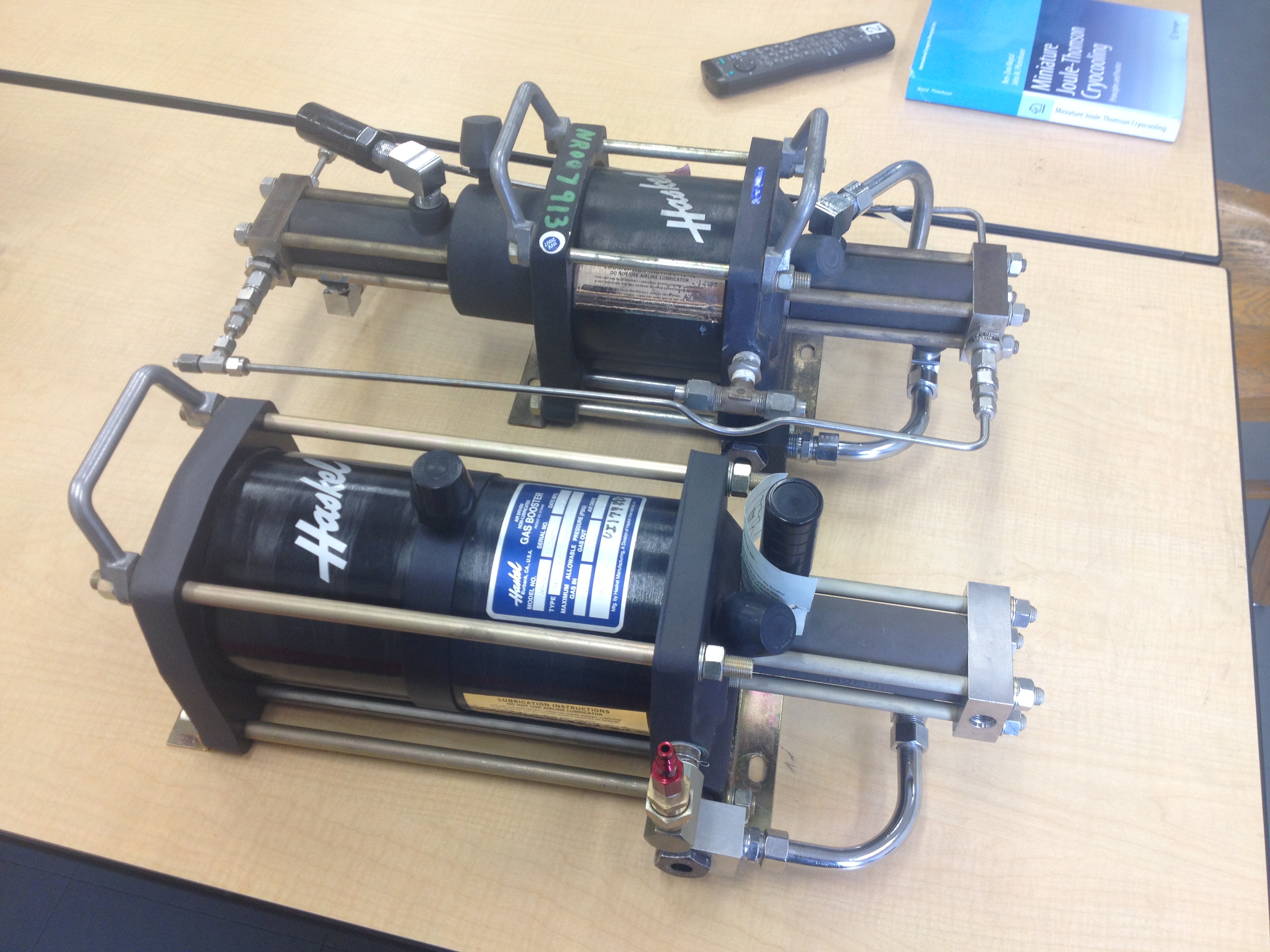
A gas booster is a type of compressor that operates on pneumatics. An outside source of compressed air is used to drive a piston. This piston is connected via rod to a smaller piston. This smaller piston is used to compress the desired gas, hydrogen in our case. An internal pneumatic signal is used for cycling. Because of the smaller surface area of the hydrogen piston compared to the air drive piston, high pressures can be achieved. Operation is simple: if air is supplied it runs and if air is cut off it stops. The two we had were Haskel brand: an AGD-15 and an AG-152. With a 250psi air drive, the AGD booster can reach a stall pressure of 5000psi. The AG can reach 20,000psi, though with a considerably lower flow rate compared to the AGD. But the compressed air in our lab only reaches about 100psi, so we don’t get quite that high. More realistically, we can reach 1400psi with the AGD and 13,000psi with the AG.
After figuring out how they worked, I disassembled them to inspect for damaged components and to check the seals. The AGD appeared brand-new. The AG was well-used but hat no obvious faults. For safety with hydrogen applications, we elected to replace the hydrogen-piston cylinder of the AG. The material can become hydrogen embrittled, and the manufacturers suggest replacing them every 7 years. This booster was far older than that so we made the $2000 purchase. A second modification was made to the AG on the control side. It had previously been modified so that it could only run when a pressure was applied to a secondary control section, making it easier to turn on and off with solenoids. We preferred to only have a single gas source as control, so we reversed the modification. Finally, the internals of the air drive section were cleaned and lubricated and they were both reassembled.
With those improvements, the AG was ready to be used on hydrogen. I ran a test to determine stall pressure of the booster using nitrogen. After hunting leaks with soapy water, we managed to reach 1400psi easily, and 1500psi if the building’s air supply cooperated. Success! A description of the results of those tests can be found here:
https://hub.wsu.edu/ise/2016/07/29/haskel-gas-booster-pressure-test/
The AGD was ready from the start, but the high stall pressure was a concern. To keep it safe, even in the event of operator error, either all the outlet tubing had to be rated to 13,000+psi or we needed a robust pressure relief system. Preferably both. Since we had no needs for such high pressure at the time, it was decided not to do a stall pressure test of the AGD.
Otherwise, I wrote a brief manual for the club regarding how to use the gas boosters safely. It included a procedure for determining the operating conditions relating the air drive pressure, inlet gas pressure, outlet pressure, and flow rate.
Senior Design: Heat Exchanger for Hydrogen Liquefaction
Ordinarily, Senior Design is taken during the last semester of your senior year. But one of the projects for that spring (2016) was of interest to me so I took the course a semester early. The project was a continuation of the work done on the refueling station.
A heat exchanger needed to be designed for the liquefier on the cold end. After the vortex tube, hydrogen would be regeneratively cooled by a heat exchanger before being throttled through a valve. Unliquefied hydrogen would then exit through the other end of the heat exchanger providing cooling. This section after the vortex tube could be modeled as a Hampson-Linde cycle. The client’s recommendation was to use a unique design comprising two copper tubes brazed together. Though not quite as efficient as a tube-in-tube heat exchanger, previous experiments suggested it was still extremely effective due to the higher thermal conductivity of copper at liquid hydrogen temperatures. This design could be made entirely in-house and did not require a custom fitting that would need to withstand 1400psi at liquid hydrogen temperatures (as would be needed for a tube-in-tube heat exchanger). It would also need to fit inside the mouth of a specialty dewar (about 6” in diameter). By doing this, we could keep the heat exchanger inside the vacuum system, eliminating the need for a separate vacuum chamber.
The numerical needs were, again, greatly varied. Part of the difficulty lied in the performance of the vortex tube: though we knew it produced a cooling effect, there existed no numerical model for predicting performance at arbitrary inputs. So, we designed the heat exchanger to operate at various worst-case scenarios, recognizing that a length slightly longer than necessary was acceptable. In EES (Engineering Equation Solver), we modeled the heat exchanger using the NTU method and a thermal resistance network for the heat transfer coefficient. For the vortex tube, we included two coefficients: a flow fraction (hot vs cold flow rate) and a pressure drop ratio plus a cold vortex outlet temperature. This way, the user could easily modify the system with new data on the vortex tube’s performance. A stainless steel flange was also designed with bulkhead passthroughs to mount our system to the inside of the dewar.
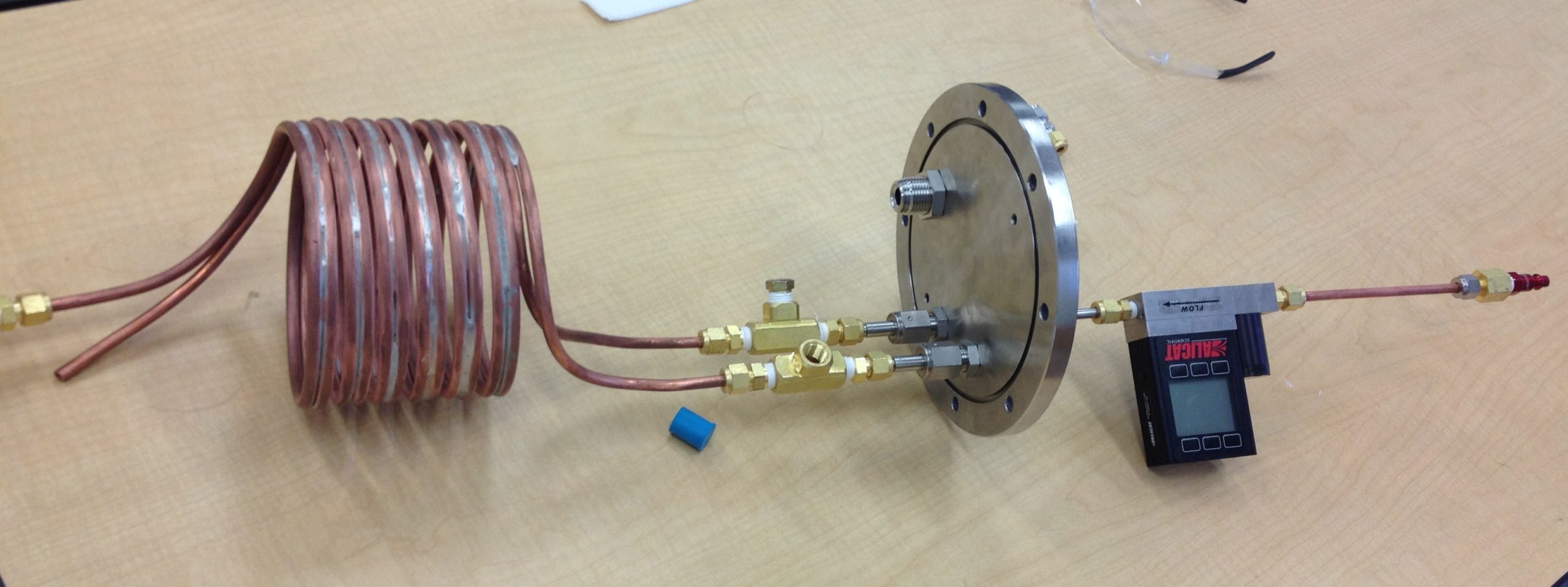
Ultimately, a 2.5 meter heat exchanger was accepted and brazed together. The flange was machined at the ProShop in Dana. To test, compressed air entered the hot side of the heat exchanger. Afterwards, it was cooled with liquid nitrogen and sent back out the cold side. Thermocouples and a flow meter measured fluid properties. In these conditions, a 90% effectiveness was predicted and 92-97% effectiveness was obtained (the flow rate was imprecisely measured). We conclude that this discrepancy was the result of conservative estimation of the thermal resistance of the heat exchanger, a reasonable assumption considering the novel design.
Co-op With Planetary Resources
In the spring and summer of 2017, I enjoyed work as a co-op with Planetary Resources in Redmond. Representatives had visited WSU on Space Day and I had been a part of the tour. They were impressed with my knowledge of the gas boosters and brought up the opportunity. Though my aerospace experience was minimal, I was excited with the chance to learn more about spacecraft systems.
While there, I worked on numerous projects supporting their objectives. I won’t go into too much detail for obvious reasons, but I’ll list a few accomplishments:
- Wrote testing procedures for loading, testing, and unloading pressurant for spacecraft propulsion system and attitude control. Ran said procedures. Characterized pressurant during thrust event. Involved use of helium leak sniffer and compressed helium bottles, vacuum pump, refrigerant compressor, thermal chamber, and Arduino-controlled solenoids.
- Designed boilerplate payloads in SolidWorks for vibration testing. Drafted technical drawings for machining per ASME Y14.5 – 2009.
- Ran load analyses of bolted joints and spacecraft separation system.
- Modeled thermal properties and designed tank/piping system for supercritical xenon propellant including pressure drop in piping and tank heating needs.
- Modeled spacecraft perturbation torques for deep space mission, primarily SRP (solar radiation pressure). Developed needs of RCS (reaction control system) thrusters and reaction wheel array. Tabulated lists of commercial options for primary thruster and desaturation thrusters.
- Modeled launch vehicle interiors and component exteriors in SolidWorks for volume budget and positioning.
- Developed first-order estimate for mass and power needs of in-orbit hydrolox propellant depot. Taught basics of hydrogen properties and liquefaction.
A few lessons learned:
- The importance of documentation: The other engineers at Planetary were excellent role models in taking good detailed notes. Not only does this help with communicating with others, it is vital for figuring out what happened, when something goes wrong.
- Be clear with your boss how you are trying to solve a problem. They might prefer you use another method. This saves time by preventing easy mistakes early.
- Ask plenty of questions and ask them often. Ask to look at previous work to get an example of how they want it done. A pretty obvious lesson, but something I thought I was better at than I was.
Since leaving Planetary, applying these lessons has been a major part of my self-improvement.
Return to the Lab
On return to the lab, I recognized several areas in cryogenics which I desired to learn more about. Most of my previous work had been on low-budget or improvised systems: in-house heat exchangers, throttle valves, cryogel primary insulation, soapy water for leak checks. But I had done little with “proper” equipment like vacuum chambers, cryocoolers, and helium leak detection. What kind of thermal paste works well? How about epoxies for wire passthroughs? As fortune would have it, Carl Bunge, a graduate student, was in need of assistance for running his experiments in CHEF (Cryocatalysis Hydrogen Experiment Facility). The purpose of this experiment was to test a ruthenium coated vortex tube for use as cooling for boiloff hydrogen gas. The ruthenium acts as catalyst to move the ortho-para ratio of hydrogen towards its equilibrium quickly (where it might otherwise take days to reach equilibrium). As hydrogen warms, the equilibrium radio of ortho increases. Since the reaction from para to ortho is endothermic, having a catalyst to force this change can be used to create more cooling than the vortex tube can achieve on its own.
We spent ages leak-checking, using helium gas and a high precision helium sniffer. Whenever possible, we used liquid nitrogen to test new joints and passthroughs to ensure cold leaks were found early. Even then, we came across many cold leaks when trying to cool down the system for testing and would have to warm up the device and start all over.
I followed procedures for filling CHEF with hydrogen while handling compressed hydrogen bottles and using control manifolds. (LH2 tanks filled passively by condensation)
When full, Carl and I would run a test, always making sure to review the procedure beforehand. We managed the heating of the tank (to induce boiloff), the warming of this boiloff gas to the desired test temperature, and maintaining hotwire temperatures with a variac. All while monitoring for sudden tank temperature rising as an indication of the last of the liquid boiling off (to end the experiment before sensitive electronics are damaged by the sudden lack of cooling.
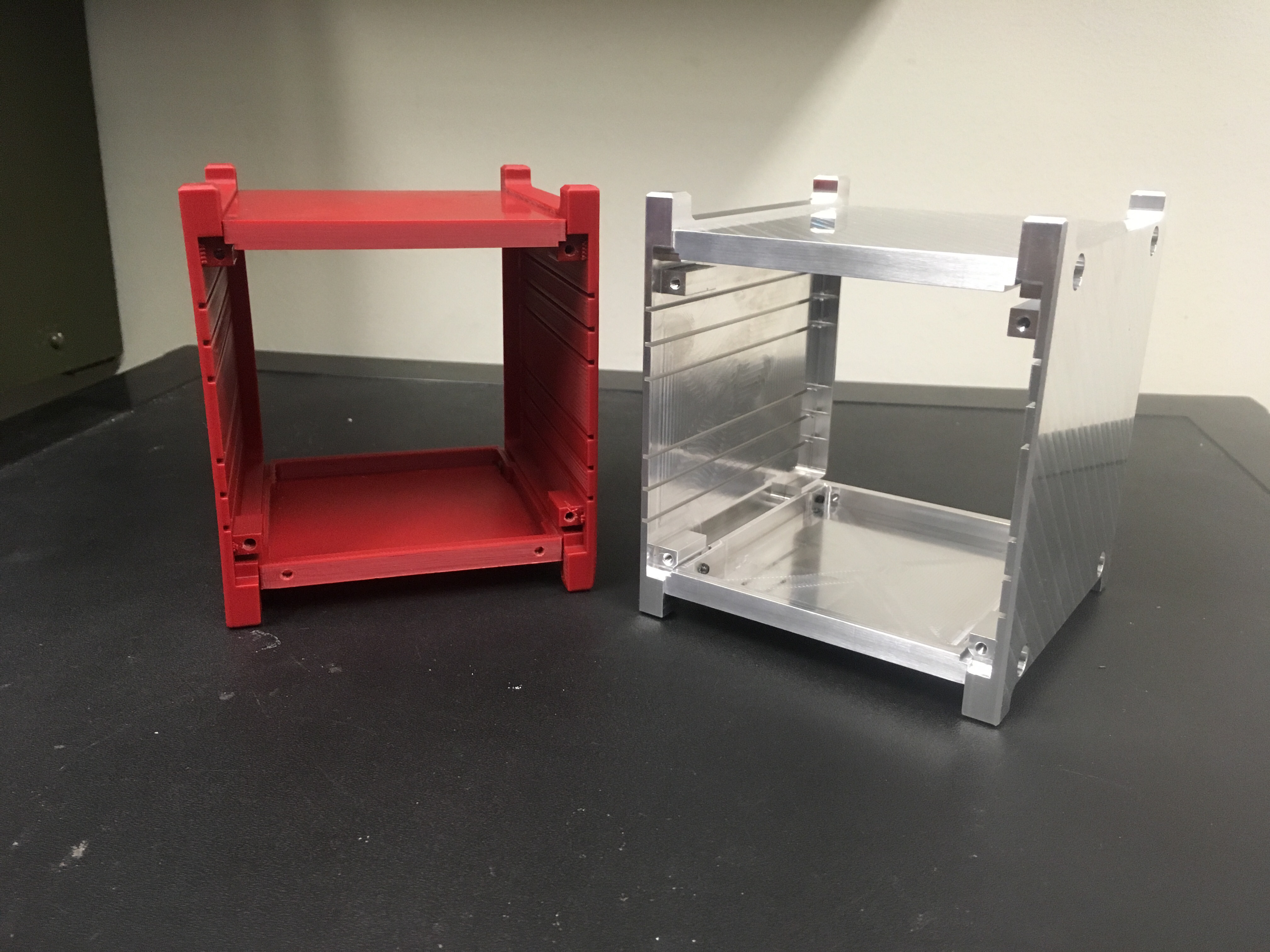
Otherwise, we built a calibration apparatus for all of the RTDs in our experiment. This required the construction of a new MLI shield, copper tower, 316 SS shelves.
I continued to work in ISE, helping organize the club in the continuation of their work on the refueling station. I led the team in developing further liquefaction models (mostly for nitrogen testing) using EES to determine refrigeration capacity and excel to estimate heat leakage. I also guided the team in designing the vent lines and vent stack. Though I had improved my documentation skills at Planetary, this is the point where it really hit me. The documentation my team had for the design and analysis of the heat exchanger was uninspiring. Images were not always labeled and the reasons for certain design features were unclear. In response, I began documenting in better detail how the system was designed, analyzed, and tested.
In the meantime, I discovered that Swagelok sells “bored-through” connectors which can be used for heat exchangers. These allow one tube to pass all the way through the connector while retaining a seal around it. This nullified our previous concern about producing our own high-pressure fittings and will allow us to produce tube-in-tube style heat exchangers more cheaply than the brazed ones. I wrote a brief report describing its abilities and construction for the next time our lab needs a heat exchanger.
Taking inspiration for work done at Planetary, I took it upon myself to build up the lab’s documentation on Safety Data Sheets (SDS). As with most universities across the world, ours had insufficient documentation on stored chemicals. I scoured through two lab spaces to document and categorize some 175 chemicals. SDS were obtained and printed and organized, except for a select few that were either unlabeled or had no SDS which were disposed of through the university in accordance with their rules. These SDS, as well as suggestions for better chemical safety, were collected into binders.
Graduate Research
Working with Carl on CHEF, I learned enough about graduate school to be comfortable applying. My graduate research would build upon this previous work: cryogenic vortex tubes for liquid hydrogen applications.
Anytime a cryogenic liquid is being stored without active cooling, heat leak causes the liquid to slowly boil off, a major source of waste. For liquid hydrogen, the boiloff rate can be decreased if the conversion from parahydrogen to orthohydrogen can be utilized to cool the ullage space of the tank. Vapor temperatures of a liquid hydrogen tank can reach 50-60K or possibly higher (compared to 20-30K for the liquid, depending on pressure). Equilibrium orthohydrogen concentration increases from ~1% to upwards of 40%, and the conversion from para to ortho absorbs heat, creating a cooling effect. So, by converting some of the boiloff gas from parahydrogen to orthohydrogen, cooling is produced, which can be used to cool the remaining gas in the ullage via heat exchanger, thus reducing boiloff. My graduate research has focused on using a vortex tube as the catalytic reactor for such a system, known as a Heisenberg Vortex Tube.
Since experiments take a lot of time and energy and money, it is useful to supplement them with computational simulations. But those computational models must be validated experimentally to an extent. I started by building a room-temperature testing setup and then experimenting with commercial vortex tubes. Then I could validate a computational fluid dynamic (CFD) model in StarCCM+ to meet experimental performance. Subsequently, cryogenic hydrogen vortex tubes were modeled after Carl’s experiments, including the para-ortho conversion. For the CFD to run accurately, this required real-gas properties, which were tabulated using Python code and the CoolProp libraries. Example code can be found here. Further simulations were run on cryogenic hydrogen vortex tubes at higher pressures (more than 1000psi) in preparation for future experiments on CHEF.
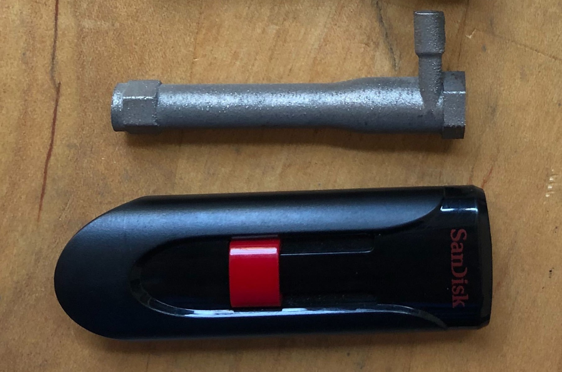
Since building a high pressure vortex tube could prove to be a challenge, the opportunity to have one additively manufactured was investigated. Such a tube could be manufactured in one single piece and orbital welded to VCR fittings, making it easy to build and install with fewer sealing points. A miniature vortex tube measuring only 50mm long with an inner diameter of 6mm was designed with a single (1.2mm by 0.7mm) inlet and additively manufactured in titanium. In testing with air at ambient conditions, it proved successful at producing cooling. Temperature was shown to drop by 13°C at a pressure ratio of 4, generating 4 watts of cooling. This, too, was modeled computationally, and the turbulent Lag Elliptic-Blending turbulence model was found to agree well. This resulted in a paper accepted by the ASME Journal of Thermal Science and Engineering Applications called “Experimental and Numerical Investigation of a Miniature Additively Manufactured Vortex Tube”.
Furthermore, parametric modeling of a heat exchanger in the ullage space of a liquid hydrogen container was developed in EES, comparing a catalyzed vortex tube to an Ionex packed bed. Factors such as fin spacing and tube diameter were varied, and the required length, subsequent pressure drop, and available cooling power were calculated. This required using functions for fin efficiency, forced and natural convection, and packed-bed flow factors.
Outside of the Lab
Besides working in the hydrogen lab, I’ve helped lead Cougs In Space (WSU’s first CubeSat team) since fall 2017. From a leader’s point of view, I noted a couple difficulties regarding leader-engineer communications:
- Engineers tend to spend too much time trying to design the first model before being reviewed. This is how it’s done in school: find an answer and then turn it in and forget about it. But for complex problems with varying goals you need prompt feedback. The first plan doesn’t need to be perfect. Just get a rough model and give it to your superior with the proper explanation of what you did and how. They’ll give you feedback to help you improve it and the work will go faster than if you tried to provide your own feedback all the time. Otherwise you’ll end up in a loop of “I’m almost done”, “I’m almost done”, “I’m almost done,” as they try to perfect it without someone else’s review.
- Some students and young engineers avoid problems if they don’t know how to solve it. They either beat around the bush or try to call it finished before it is done. Again, this comes from how we learn in school: find the formula in book and crank out a couple numbers and call it good. But there is an endless list of topics not taught in the curriculum for lack of time. Ideally the student would ask the instructor for advise on how to solve it or where to look for the proper equations. But it is also the leader’s job to recognize when this is happening and alleviate it. Help them find the right questions to ask.
Outside of engineering, I enjoy cooking. I’ve been experimenting with bread recipes, including whole wheat and sourdough. I’ve even brewed several batches of mead and wine. But, learning from engineering, I’ve maintained detailed documentation of each recipe: the procedure followed, what works or doesn’t, and suggestions for next time.