Additive manufacturing (AM) has emerged as a viable method for part production. Pieces can be made out of either plastic or metal composites, and this method of production is gaining popularity throughout industry. There are vast opportunities within cryogenics for the use of AM which have yet to be explored. Within HYPER, AM is being used for part manufacture on the Tank, and for a novel heat exchanger for hydrogen liquefaction on MHGU. This post is a guide to designing for AM, with cryogenic applications in mind. It will guide you through steps to save you and your team time, money, and most importantly- sanity.
STEP 1: Why use additive manufacturing and how does it work?
Additive manufacturing, specifically direct metal laser solidification (DMLS), is an attractive method for metal part production. Industries may use DMLS versus traditional metal fabrication for the following unique characteristics:
- Multiple part consolidation,
- Geometric freedom,
- Biomimicry,
- Optimized material densities,
- Improved function,
- Reduced waste, and
- Efficient workflow.
An example of two versions of a heat exchanger for hydrogen liquefaction, one made using traditional methods of manufacturing and the other using additive manufacturing, are shown in Figure 1. The photo on the left shows the first-generation design. It was manufactured using traditional techniques and consists of a copper tube wrapped around two aluminum collars. The photo on the right shows the second-generation design. It’s made of AlSi10Mg and has vastly increased complexity. The two collars from the first-generation design were consolidated into one part, the geometry of the second-generation design was freeform, the second-generation design mimicked the structure of tributaries, and the second-generation design minimized both waste and manufacturing time. The second-generation design could not be achieved using traditional manufacturing and resulted in vastly increased system performance.
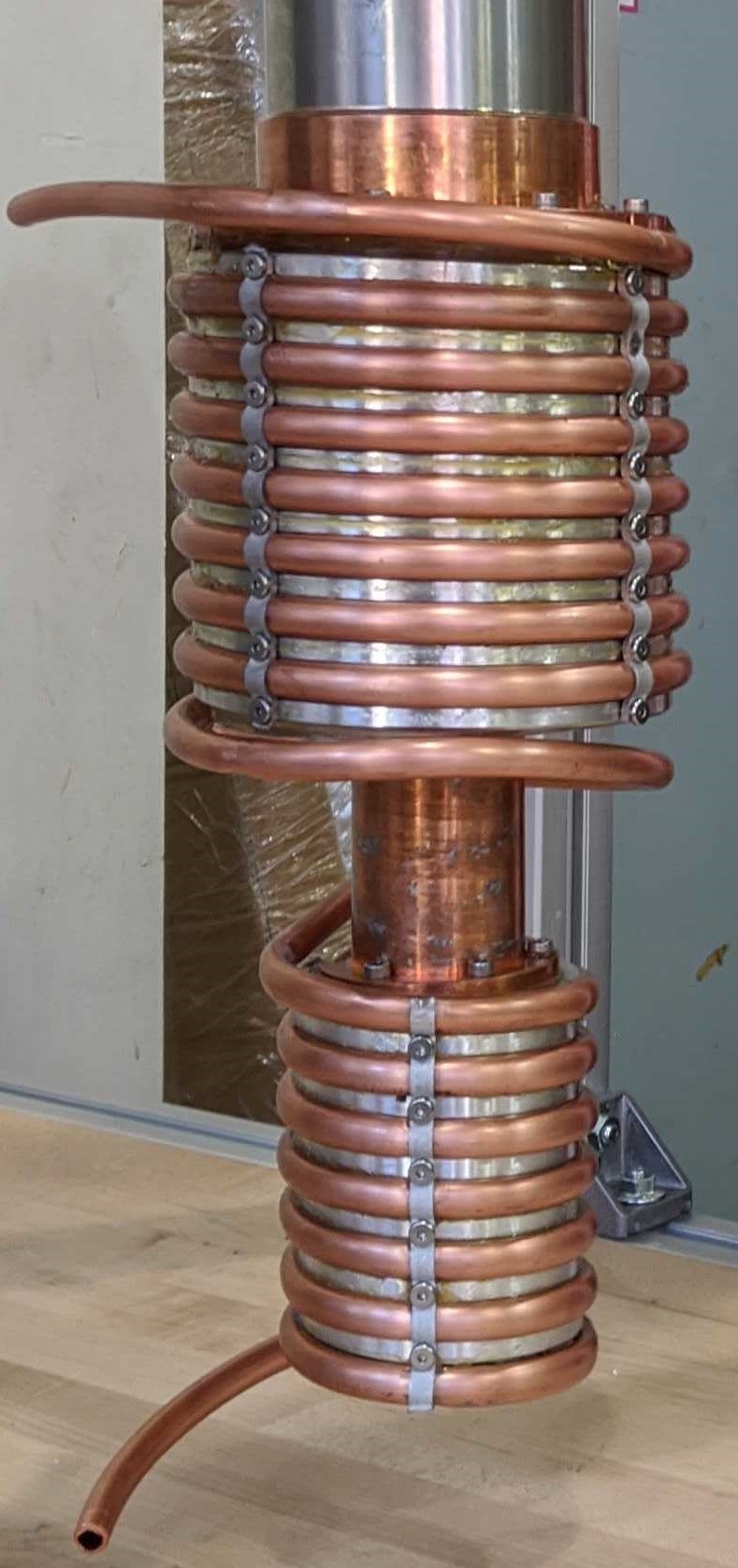
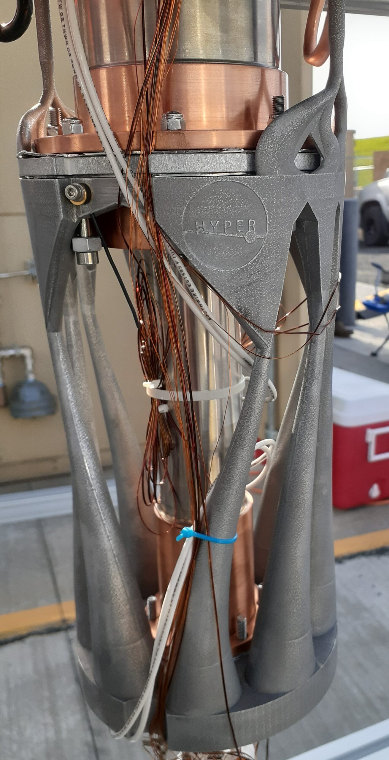
Figure 1: Left – First-generation design of a heat exchanger for hydrogen liquefaction using traditional methods of manufacturing.
Right – Second-generation design of a heat exchanger for hydrogen liquefaction using additive manufacturing.
DMLS utilizes high power (400-500 Watt) lasers to fuse tens of thousands of metal microlayers from a metal powder bed to extrude a three-dimensional part. Companies such as EOS and Reinshaw offer AM systems that use 1-4 lasers, ranging over print volumes of 228x228x190 mm to 400x400x400 mm. These systems allow for tolerance precision down to two thousandths of an inch and a layer thickness of 20 or 40 microns depending on the powder being used.
STEP 2: Is there a compatible powder for the desired application?
Material compatibility is always a factor when designing a new part, especially in cryogenics. Whether it be hydrogen compatibility, yield strength, conductivity, or ductile-to-brittle transition temperatures, the material properties will determine if AM is an acceptable method of production. For example, the MGHU second-generation heat exchanger (Figure 1, right) needed to be made out of a material that was hydrogen compatible and the design was so complex that traditional manufacturing was not an option. Aluminum was chosen due to the favorable thermal properties compared to copper or steel and hydrogen compatibility. From there, potential alloys were explored. The two main contenders were AlSi10Mg and Al6061. Only Al6061 is known to be hydrogen compatible, but it is newer to AM and therefore no manufacturers felt comfortable completing the task. The material properties of AlSi10Mg were investigated by experts in the field and it was determined that the material would likely be suitable, although the thermal properties would not be as favorable. If no aluminum powders had been deemed suitable, copper options would have been explored next.
The following is a list of just a few of the metal powders that are currently available. Those known to be hydrogen compatible include 316 SS and 6061 Al. It is highly recommended that a manufacturer be contacted before beginning design to discuss material selection and obtain material specification sheets.
- Stainless Steel
- 316, 304L, 17-4 PH, 15-5
- Titanium
- 64
- Aluminum
- AlSi10Mg, AlSi10, 6061
- Nickel Alloys
- 625, 718, K500, super alloys
- Copper
- GRCOP-84, GRCOP-42
- Cobalt Chrome
- Maraging Steel
STEP 3: Post Processing
Think ahead to the final stage of manufacturing the part. Tasks such as thread tapping, surface finishing, or filleting are completed by machining, therefore appropriate mounting points must be considered. Support structures and powder must also be removed from the system. In addition, the surface finish may need to be modified. The surface roughness is a function of the layer thickness and post processing may be required depending on the application.
Chemical processes may be used during post processing of non-metal parts to remove support material or during post-processing of metal parts to achieve desired material properties. If designing for a cryogenic application, the chemical processing may make the part unusable if the chemical cannot be completely removed and is not compatible with the cryogen. This should be discussed with a manufacturer.
An example of designing for post processing is the removal of powder from the second-generation heat exchanger. The minimum inner diameter of the tubes at which powder could be removed from the system after printing was 3.175 mm (1/8”). Ideally, the diameters in the system would be smaller, but modifications had to be made for manufacturability.
STEP 4: Designing for Additive Manufacturing (DfAM)
DfAM starts with an overall feature scope. Note the size, orientation, complexity, and support of each feature when drafting up ideas. The requirements to ensure that the part model can be successfully manufactured are outlined below.
1. Rule of 45: Any angle measured from the horizontal must be greater than 45°. Smaller angles will require support material
a. To achieve the best surface finish, the print angle must be greater than 60°.
b. All surfaces with print angles greater than or equal to 45° can be printed without the addition of support material.
c. If the print angle is less than 45° support material must be added
d. Chamfers can be added to overhangs to reduce the amount of support material required.
The following images illustrate the rule of 45. Figure 2 shows how to measure print angles. Figure 3 shows how the same surfaces are displayed drafting tool is used. Figure 4 shows the same surfaces as displayed while using the gradient drafting tool.
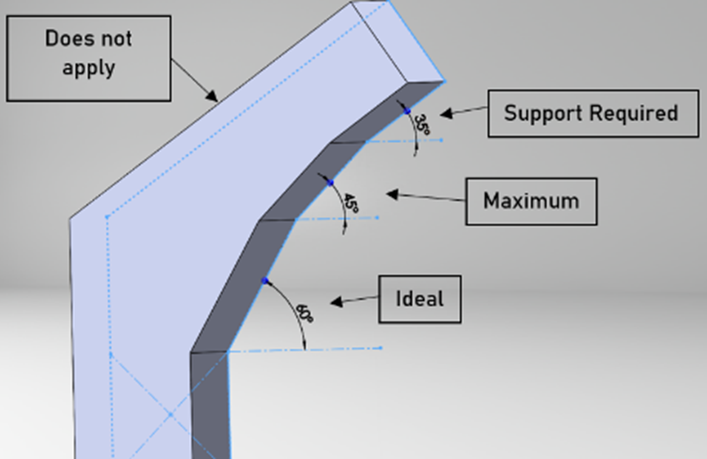
Figure 2: Image showing how to measure print angles. It shows an ideal print angle, the minimum print angle that can be done without support material, and an angle requiring support material.
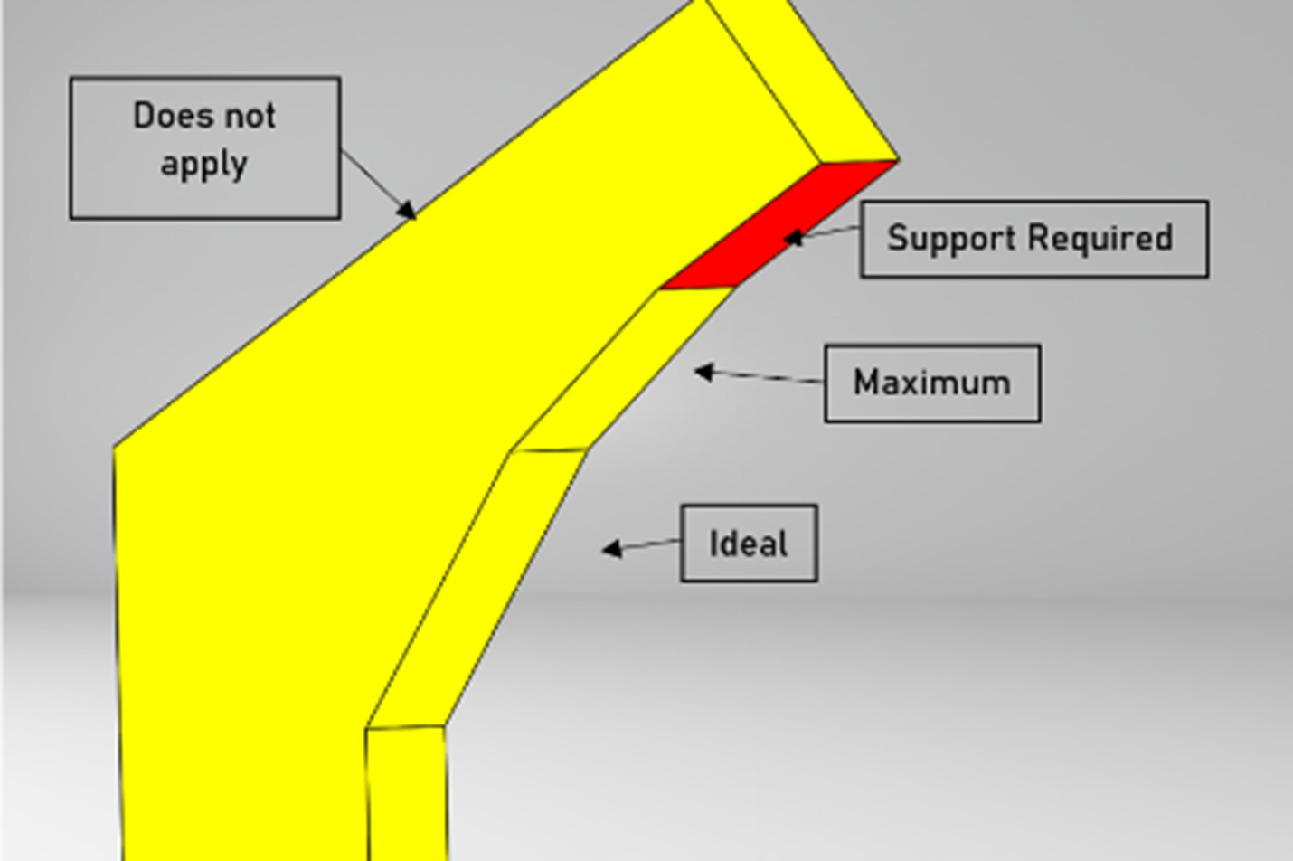
Figure 3: Image showing how the draft tool displays surfaces which need support material.
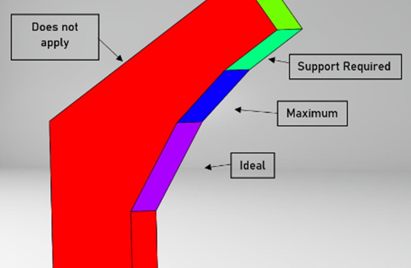
Figure 4: Image showing how the gradient draft tool displays surfaces which need support material.
Chamfers can be added to overhangs to reduce the amount of support material required. Figure 5 shows an overhang requiring support structure without a chamfer. The gradient draft tool is used. In Figure 6 support structure is added. There is a decrease in the amount of area requiring support shown in green.
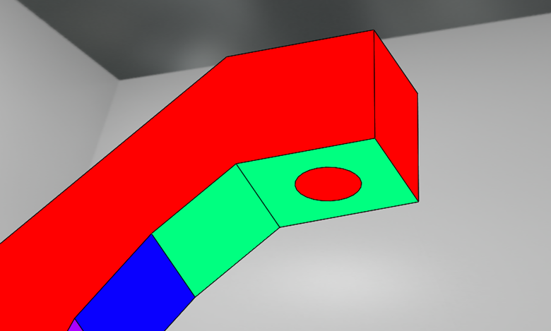
Figure 5: An overhang without a chamfer, shown using the gradient draft tool.
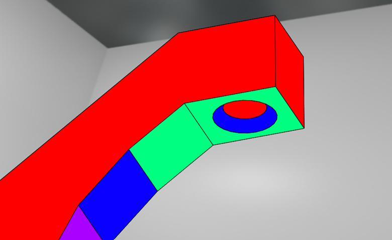
Figure 6: An overhang with a chamfer, shown using the gradient draft tool. The problematic area, shown in green, decreases.
2. Feature Precision
a. The minimum achievable part size is related to the laser spot. Laser energy is focused in one location, but heat conducts to the neighboring powder. This is illustrated in Figure 7. As a result, the minimum achievable part size is slightly larger than the laser spot being used. The difference in size is dependent on the powder being used and the associated thermal properties.
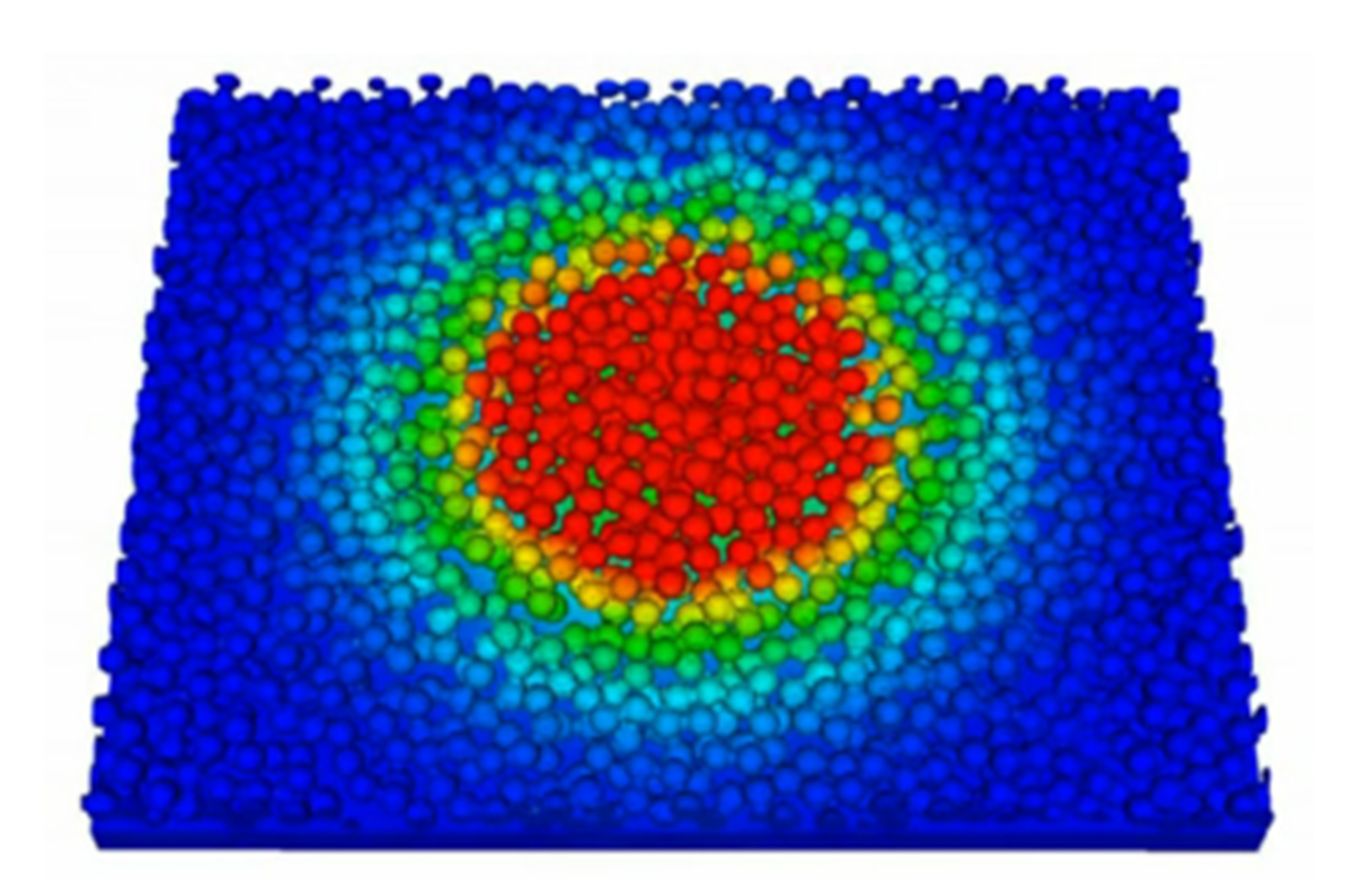
Figure 7: Thermal image of heat distribution from a laser in metal powder. (Saunders M 2016 DfAM essentials – print parts efficiently and effectively. (LinkedIn: LinkedIn.com), https://www.linkedin.com/pulse/dfam-essentials-print-parts-efficiently-effectively-marc-saunders/)
b. Be aware that internal stresses are imparted in the part as a result of printing. Some treatments can be done to relieve this stress, but it must be noted that more delicate parts have a higher chance of failure as a result.
c. The machine being used will impact the spot size, and therefore the achievable geometry. Not all manufacturers have all printers. Make sure to check that a printer is available that can achieve the desired specifications.
d. Surface roughness is generally proportional to layer size, which is linked to the powder being used. Smoother surfaces can be achieved by decreasing the layer size, which increases print time as well as cost.
3. Arcs, Holes, and Protrusions
a. To avoid adding support material for arcs, a 2:1 ellipse height to width ratio should be used. This is shown in Figure 8.
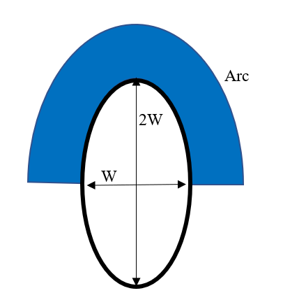
Figure 8: How to construct an arc to minimize support material.
b. Vertical holes print cleaner than those that are horizontal or angled. The top of holes that are not vertical may be flattened due to part sagging, and if the hole is too large support material may be required which may be impossible to remove. It is recommended that passages not be circular. If a passage must be circular, it is recommended that they be modified to a teardrop shape.
c. During a build, the powder is termed self-supporting, in that the layers must build on the previous structure. When the next layer goes beyond 45 degrees or significantly varies from the layer prior, there may not be enough support material and sagging can occur. This problem is exacerbated with protruding features. Support material must be added to maintain part integrity.
4. Supports
Support material is added when a part is not able to self-support during the build. The goal of a design is to minimize the amount of support material necessary for a successful build. Most often, the manufacturer will add support material as necessary. Work with the printer to make sure that there is an established plan.
a. Sometimes, added support material does not affect the functioning of the part or the supports adhere to very delicate features. In this case, it may be decided that the supports be left on the part.
b. Most often, supports are removed after printing. The supports are removed mechanically, and this can become a problem if they are attached to delicate features.
c. To minimize support material, designers should consider using the 1:2 ellipse ratio for arcs, add chamfers to critical surfaces, and remember the rule of 45, all detailed elsewhere in this document.
5. Surfaces
a. Complex surfacing such as waves or crinkles should be avoided. These surfaces add unnecessary complexity to the print and often violate the rule of 45. The surfaces may require the addition of large amounts of support material due to the odd geometry.
b. Beware of interferences between bodies or surfaces in a design. The interferences may appear unimportant because the main surface may be continuous, but the interferences will ruin the print.
6. Useful evaluation tools in SolidWorks
a. Draft analysis
- https://help.solidworks.com/2020/English/SolidWorks/sldworks/r_draft_analysis.htm
b. Zebra stripes
- https://help.solidworks.com/2020/English/SolidWorks/sldworks/c_zebra_stripes.htm
c. Import diagnostics in STEP format
- http://help.solidworks.com/2019/english/SolidWorks/sldworks/c_import_diagnostics_overview.htm
Other Useful Resources
- https://www.elementum3d.com/
- https://www.materialise.com/en/academy-manufacturing/resources/design-guidelines
- https://www.digitalengineering247.com/article/design-guidelines-for-3d-printing-additive-manufacturing/
- https://www.linkedin.com/pulse/dfam-essentials-print-parts-efficiently-effectively-marc-saunders/
- https://visserprecision.com/
- http://additivemet.com/wp-content/uploads/2016/07/design.pdf
Other Comments
- Just because a printer is able to print in a material does not mean that they have it on hand or that they have a printer in the necessary size.
- Just because a company has a suitable printer does not mean that it’s currently available. There may be a waitlist.
- Before creating a detailed design, find a manufacturer that has your designed material, a large enough printer, and a timeline that you can work with. Then, meet with their engineers early and often to go over designs that will and will not work.
Co-author: Lain Pesek