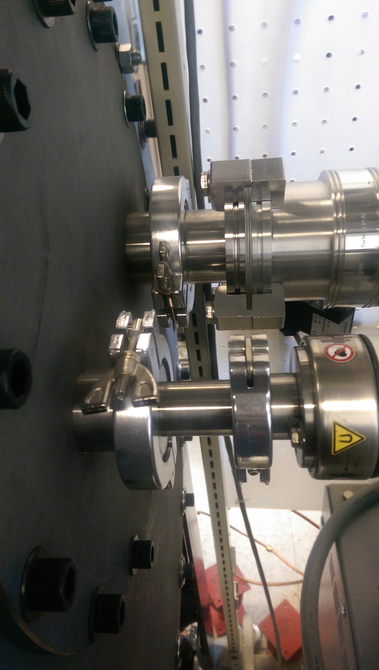
The test chamber may not be the most technically challenging or complicated part of the cryo-design, but it is arguably the most important. Without it, you have no chamber to pull a vacuum on, no enclosed boundaries for your cryocooler to take energy from, and nothing to mount your experiment to. Luckily I am inheriting an already functioning test chamber from Jake Fisher. As I noted in the first post, you must balance time, cost, and ease of design. This means that while I could design a completely new test chamber that fit the specifications for my experiment exactly, it really isn’t worth my time or money when I can adapt it to my uses. I simply need to change out some parts to make it work for me. Pictures of the test chamber/other components can be seen below.
The chamber is a cube shape comprised of 6 26 inch steel walls with a hole in each to allow from any side as well as customization for future experiments. Circular steel coverings are made for each individual hole. We can design and machine these to serve our individual purposes, such as including viewing ports for optical information, or holes to serve as ports for our vacuum pump, cryocooler, and various other needed components. Currently 4 of the 6 plates are whole and only act as coverings. The plate on the side has one hole and is where the vacuum pump systems hook into the chamber. The plate on top has two holes currently, one for the cryocooler to attach in, and one for wiring and other components to pass through. You can see the cold head on the inside to the right, one half of the copper radiation shield in the background, and the current test set up in the chamber, a twin screw extruder. For the most part I will keep the same set-up in the test chamber, putting my experiment where Jake Fishers currently is. I will get more into the details of what exact changes I am looking at in a later post.