Is machine use necessary for this project?
- Precision cutting required
- Precision hole placement
- Bulk material cut to a complex geometry geometry
- Material constraint on fabrication type
Machine Controls and Table Movement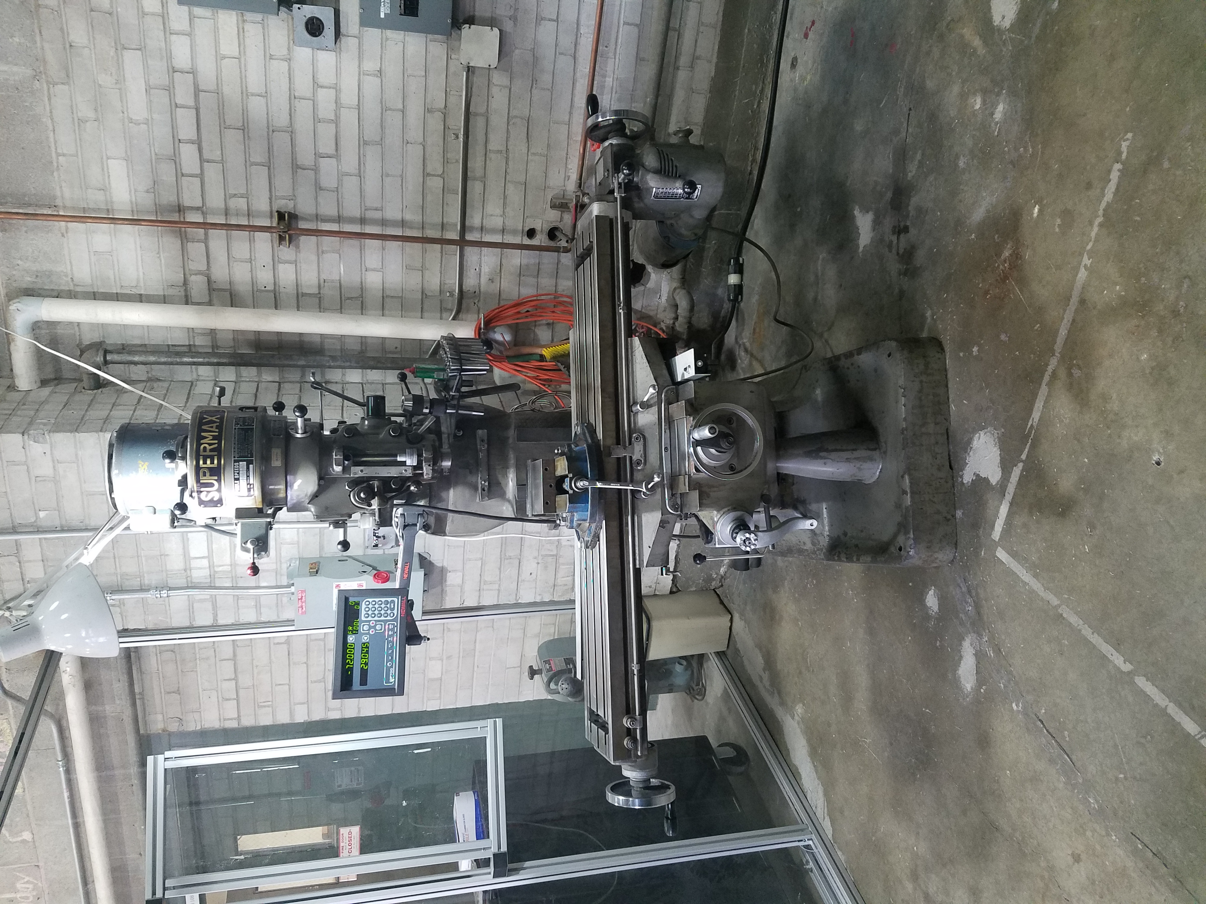
At first glance, the leavers and knobs on the mill head may seem intimidating. For most general operations though few of the controls are used making the learning process much easier. Most projects can be taken care of by using the table X, Y and Z feeds along with the quill feed handle. Eventually there will be processes that require you to learn more of the ins and outs of the machine such as head tilting or changing the mill speed. The X and Y axes movement are controlled by the two round handles connected to the base of the machine. When the X axis is referred to, the side to side travel is being referenced while the Y axis feed refers the movement of the table to and away from the user. If the table X axis of our machine is locked in place and the handle won’t turn, the culprit is likely the X axis auto feed being engaged and can be solved by disengaging the auto feed. For a video showing some basics of the machine controls please see here.
Collets and Drill Chuck
The cutting tool to be used will be held by either a collet or a drill chuck. A drill chuck is useful when you need to drill multiple holes of multiple sizes because this attachment allows you to quickly change between drill bits without changing the chuck itself. It should be noted that the chuck is meant specifically vertical holes and is never meant to be used when horizontally feeding the work piece. This is because drill chucks are meant for vertical forces but not necessarily for horizontal forces. Our drill chuck is mounted to a Jacob’s taper, this taper mount has a threaded top to attach to the quill and a tapered base that creates a friction fit with the drill chuck. Excessive work piece vibration can cause the friction fit to loosen causing the drill chuck to fall off the taper mount. If this does happen, the drill chuck must be remounted to the taper. Both surfaces should be cleaned first with a solvent such as acetone to remove any oils present that may otherwise act as a lubricant in this fit. To secure the two pieces, the top of the Jacob’s chuck should be struck onto a piece of wood that backed by a solid surface.
Collets are designed to be used with a specific cutting tool shank diameter allowing a much more secure fit than a drill chuck. Both endmill bits as well as drill bits are usable with the appropriately sized collet allowing for either drilling or horizontally fed workpieces. To mount a collet and endmill, the collet should be tightened onto the quill loosely at first without the endmill inserted. After the collet is loosely connected to the quill the endmill should then be inserted so that the cutting surface is fully outside of the collet while being supported by your hand to prevent dropping the endmill onto the mill bed. The quill is then hand tightened until the mill bit will no longer drop out, and at this point the spindle brake can be used to allow the quill to be tightened completely with the wrench stored on the machine. For a simple video showing this process and some information on mounting types see here.
Cutting Fluid and Lubricants
When available, appropriate cutting fluid should always be used on the piece to be cut. Cutting fluid when working with steels will primarily act as a coolant for the workpiece and cutting tool, cutting fluid while working with aluminum will work the same as with steel as well as preventing metal from gumming up the cutting tool. This is because Aluminum is soft and will stick to the cutting surface of the tool effectively dulling it. A dull tool cutting surface will cause higher heat, poor surface finish along with increased vibrations. For our uses, a couple drops of lubricant per inch will generally provide enough lubrication for small projects. For a quick reverence chart comparing material type, process and cutting fluid type see here.
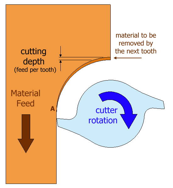
General Endmill Cutting Tips
The cutting tools that we currently have in the TFRB are all square end titanium nitride coated bits in two and four flute styles. Higher flute counts are generally used with harder materials, so if stainless steel needs to be cut then a four-flute bit should be used while a two-flute bit can be used for Aluminum. The cutting procedures can in general be broken down into slot/face milling, side milling and basic drilling. For side milling or face milling operations that do not use the entire width of the of the cutter the material should be fed against the rotation of the cutter also known as conventional milling. Climb milling will reduce the lifetime of the tool as well as potentially causing backlash in the machine. Backlash can cause the cutting bit to bind up and break either the tool or the mounting setup. “How deep should I cut?” comes up often and the answer is “it depends”. The depth of cut that should be made varies based on multiple factors such as tool diameter, machine power, material type and feed speed. In general, it is recommended that the depth of cut into aluminum is kept to less than half of the diameter of the end-mill, and even shallower for harder materials like steel. When in doubt it is always safe to take a shallower cut with more passes. A shallow cut may require more time due to more passes being required, but this also requires less power from the machine and reduces the heat load on the end-mill bit.
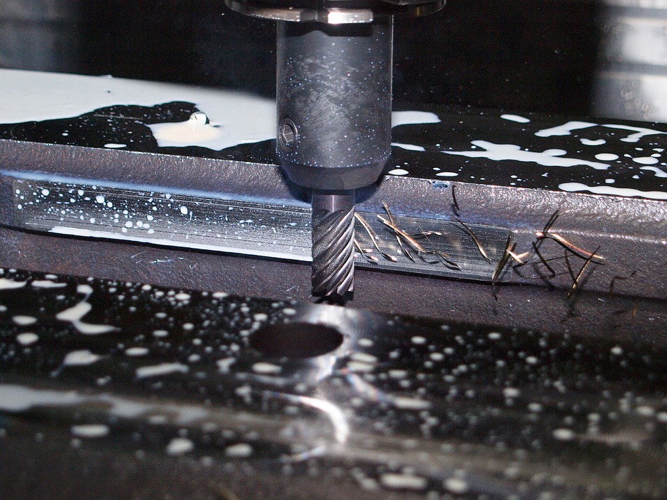
When side milling, as much of the cutting surface should be used as possible giving as deep of a cut as possible. The best situation is to have the cutting surface cover the entire side depth to be cut so that there is no material being cut by the base of the end-mill. The attached photo shows an example of the “correct” way to side mill as opposed to the less efficient side milling setup.
Drilling holes with a mill is also an option that can be performed with either a drill bit or an end-mill that is designed to be able to plunge. End-mills can plunge into the material if there are cutting surfaces in the center that are designed to cut down, but if the bit is lacking this center cutting surface then plunging may damage the bit. Because of this potential damage, it is recommended to use a drill bit when drilling into a work-piece. For a more in depth look at end mill types and general use recommendations see here.
For aditional reading material that explains each of the concepts mentioned here please refer to American Machine tool’s web page “INSTRUCTIONS HOW TO USE A MILLING MACHINE”
There are also many video tutorials available online for manual mill use that cover everything ranging from the basic use to very specific use cases. A relatively simple tutorial that should give a solid base to get started is attached to this page.