Sealing anything at cryogenic temperatures requires extremely tight tolerances. If tight tolerances are not considered, holes may open at the source of the seal, allowing cold leaks to occur as referenced in this past post. In today’s How To, we’re going to discuss how to weld tubes together utilizing orbital TIG welding. Orbital welding has given the lab an advantage in that all our welds minimize human error and the whole operation is computer automated. The system being used is Swagelok’s M200 orbital welding system, which was donated to our lab through the Boeing Cybergrant program. The procedure is as follows:
Procedure:
The first step to perform a tube weld is to prepare the two ends of the tube that will be joined together. For this example, we will be welding a .5in 316L stainless steel tube.
- To ensure a flat contact between the two tubes both ends must be chamfered using a Metabo drill with a carbide cutting tool.
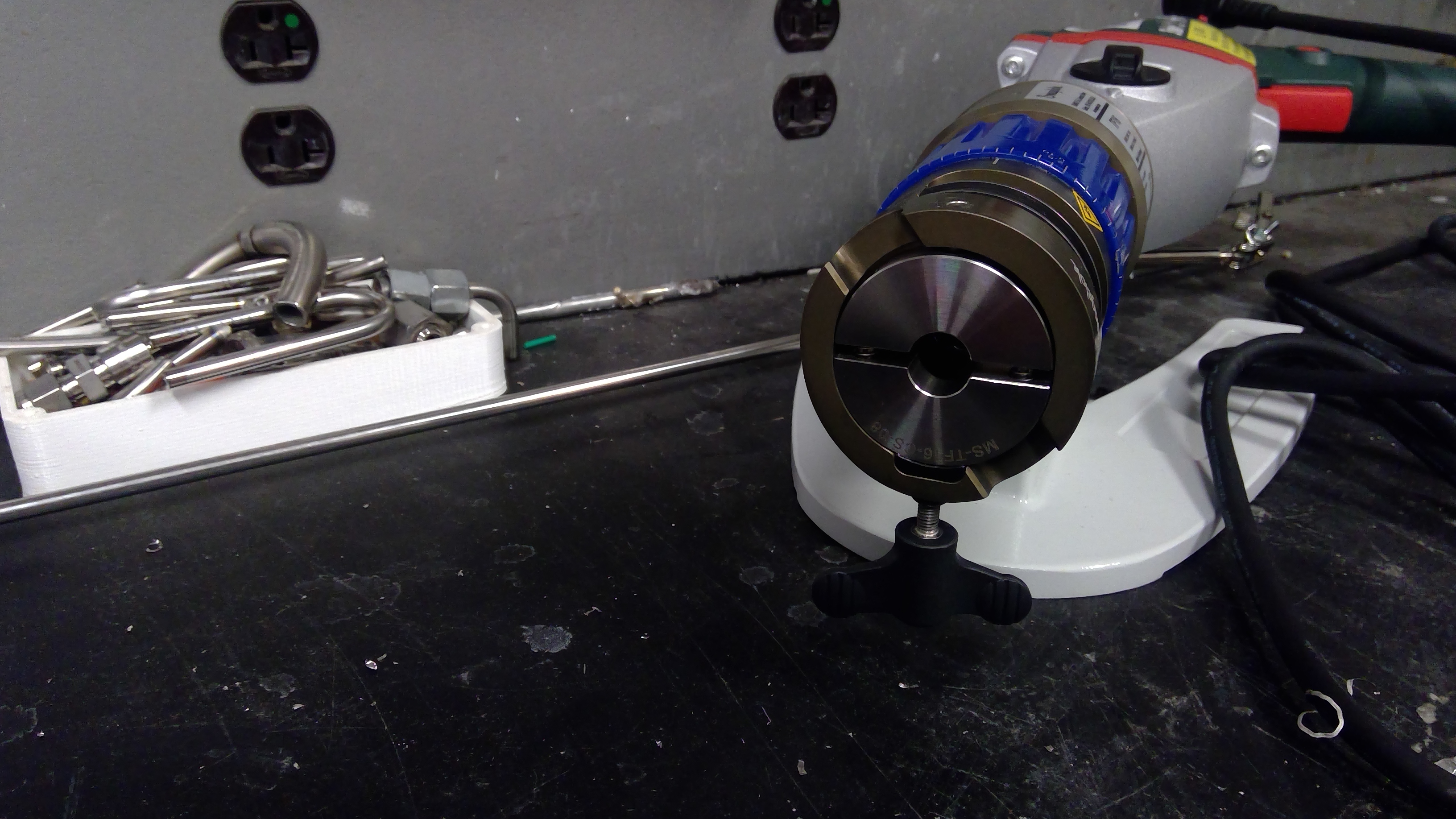
To Chamfer the tube face, insert the .5 in collet into the end of the drill.
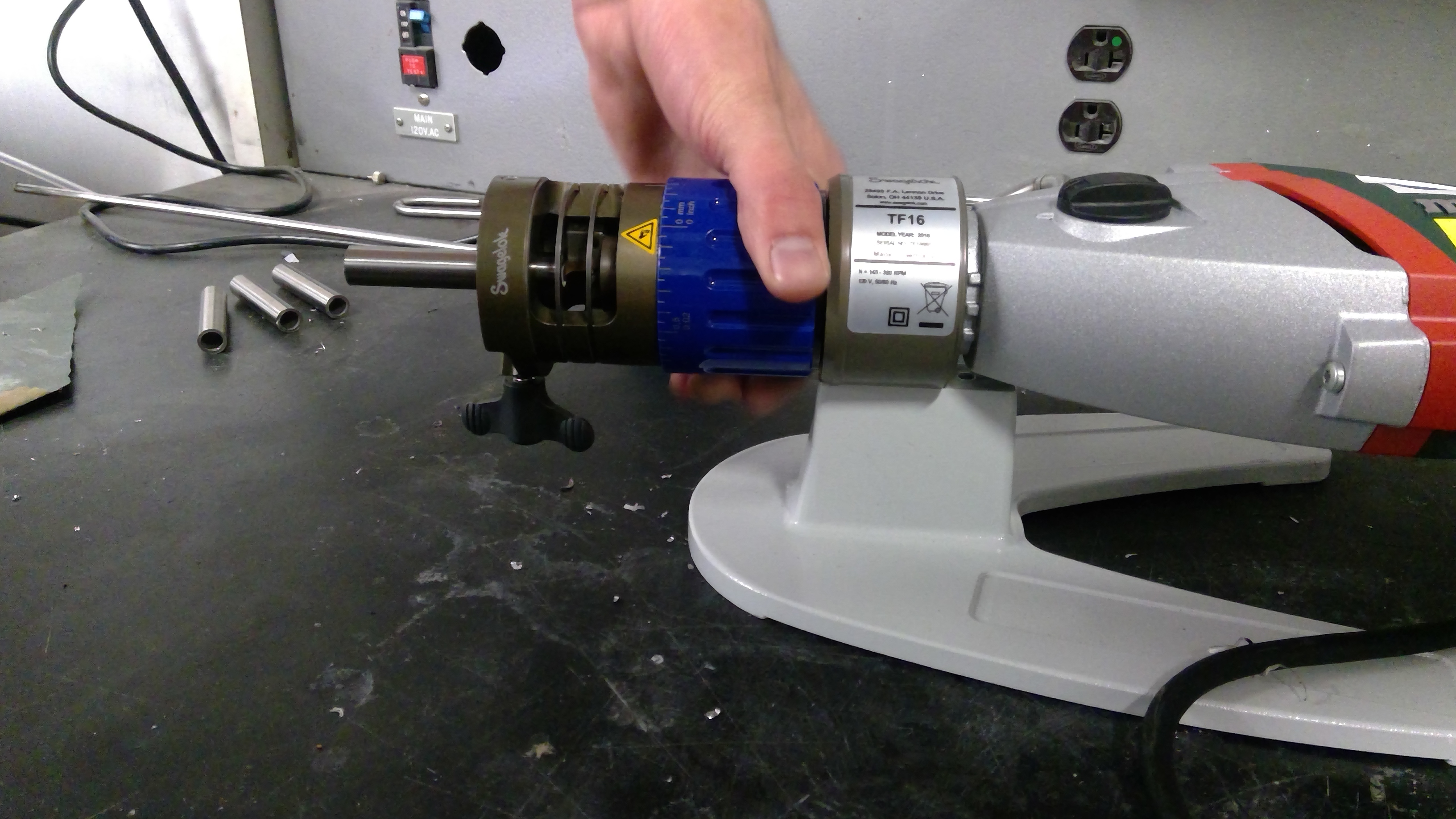
Then insert the tube into the drill and while holding the red trigger slowly turn the blue nob to cut away the end of the tube to a flat surface. Once the desired amount of material is cut back off the bit from surface of tube before releasing red nob to ensure no build up is left on the face of the tube.
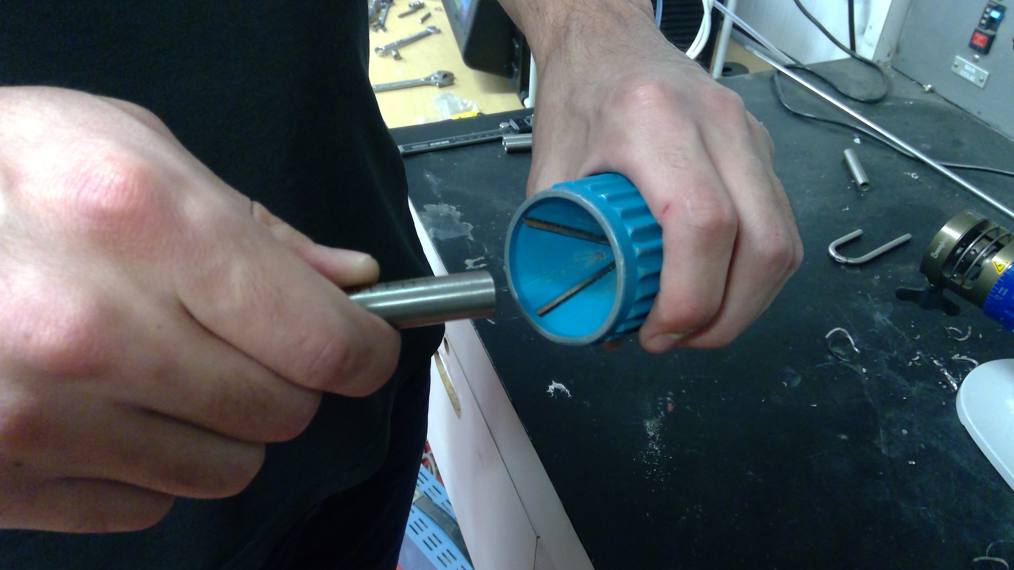
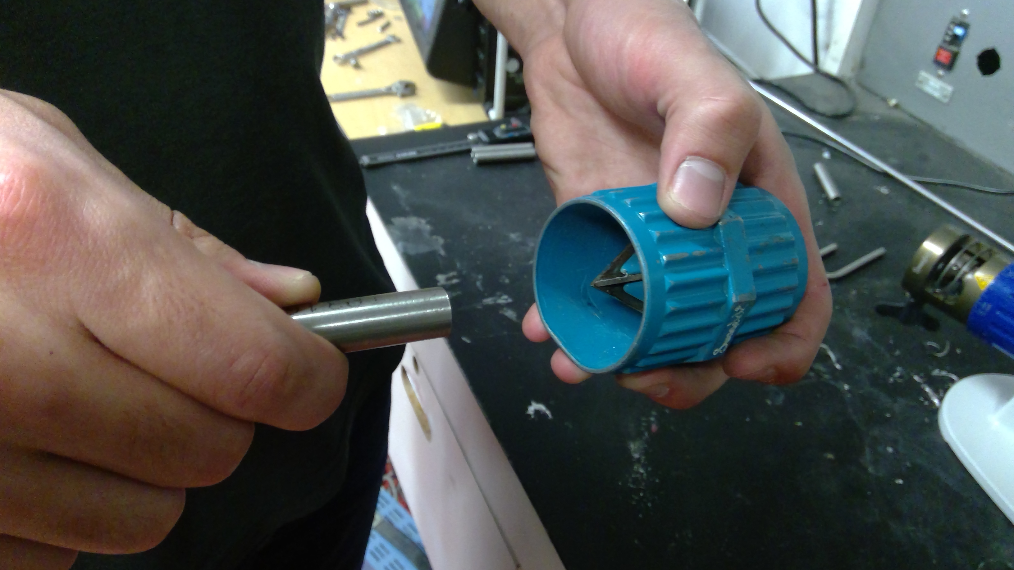
Next use the blue handheld chamfer tool to remove any burs from the inside and outside edge of the tube.
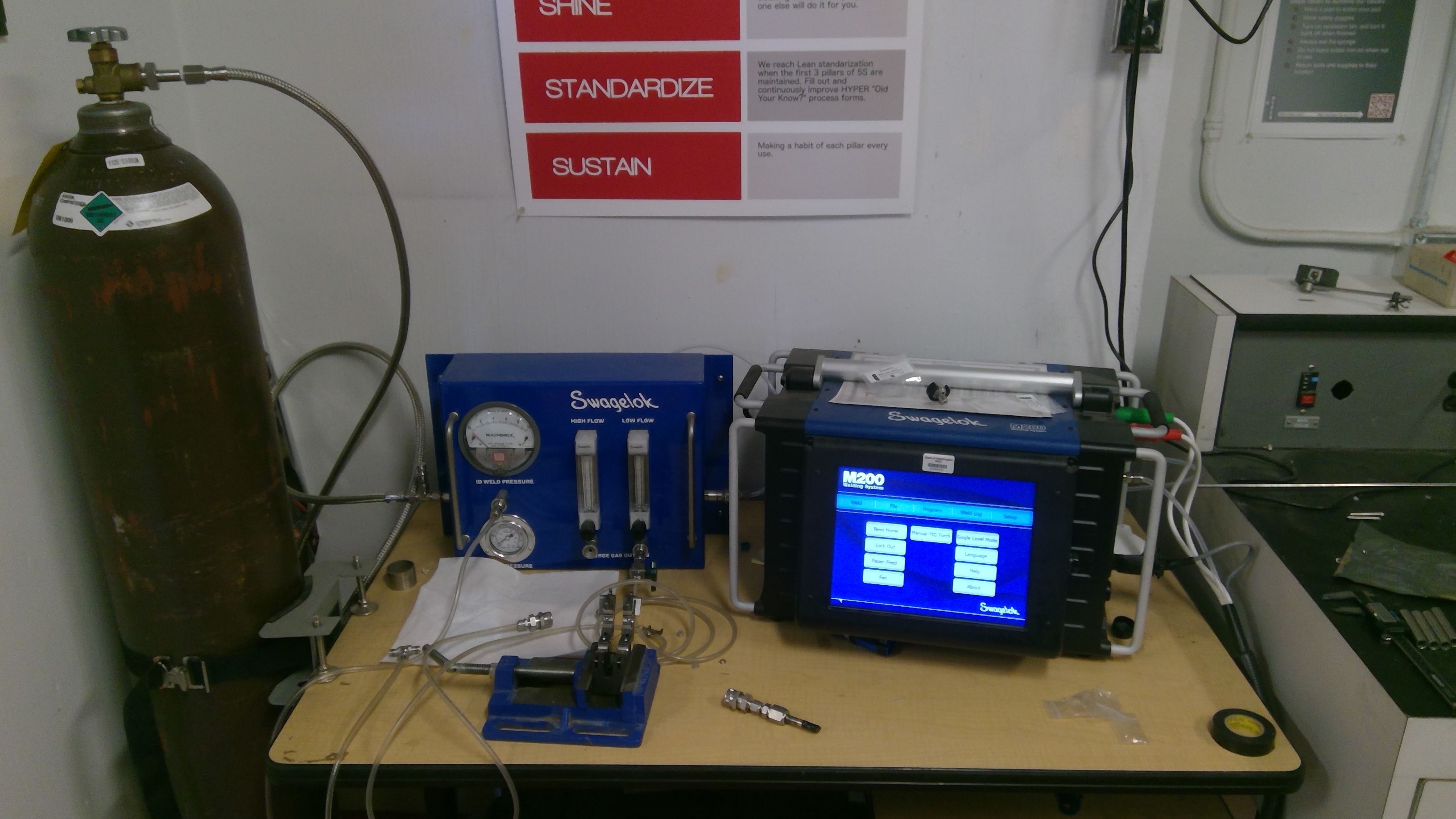
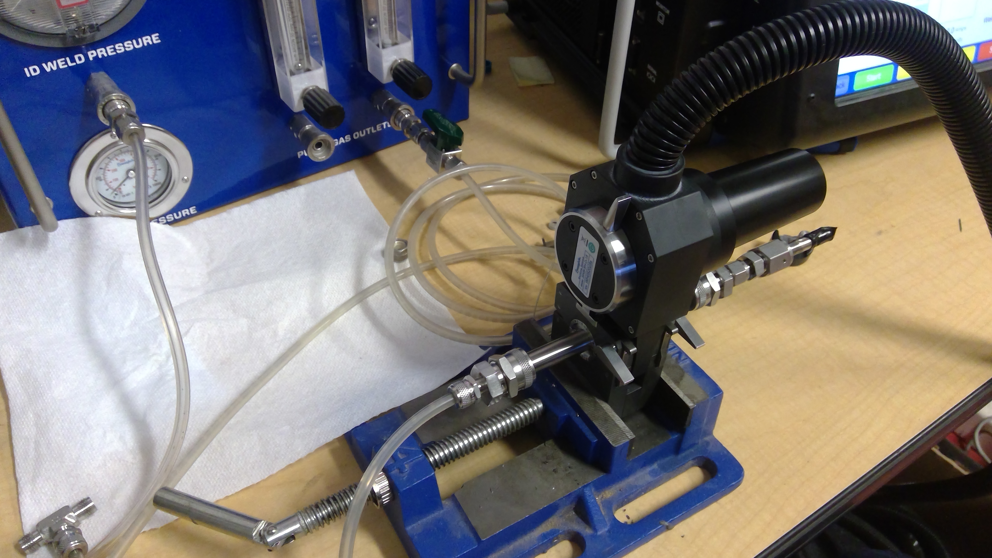
2. Now that the tubes are ready to be welded it is time to set up the Swagelok M200 power supply.
First, perform a visual inspection of the M200 power supply and ensure that it is plugged into a wall outlet and the Argon bottle is connected to the power supply.
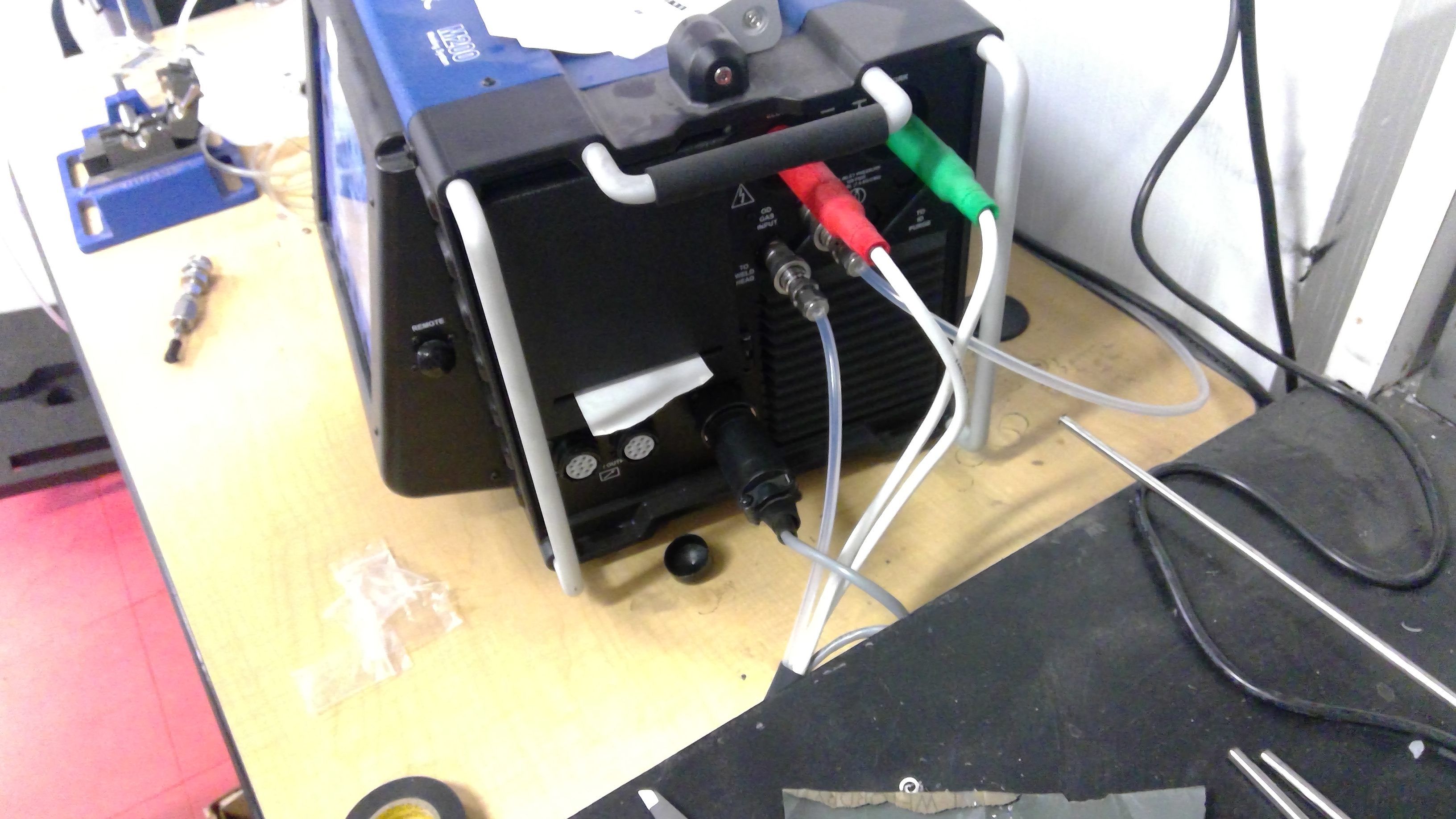
Then make sure that the weld head is connected to the Power supply like so.
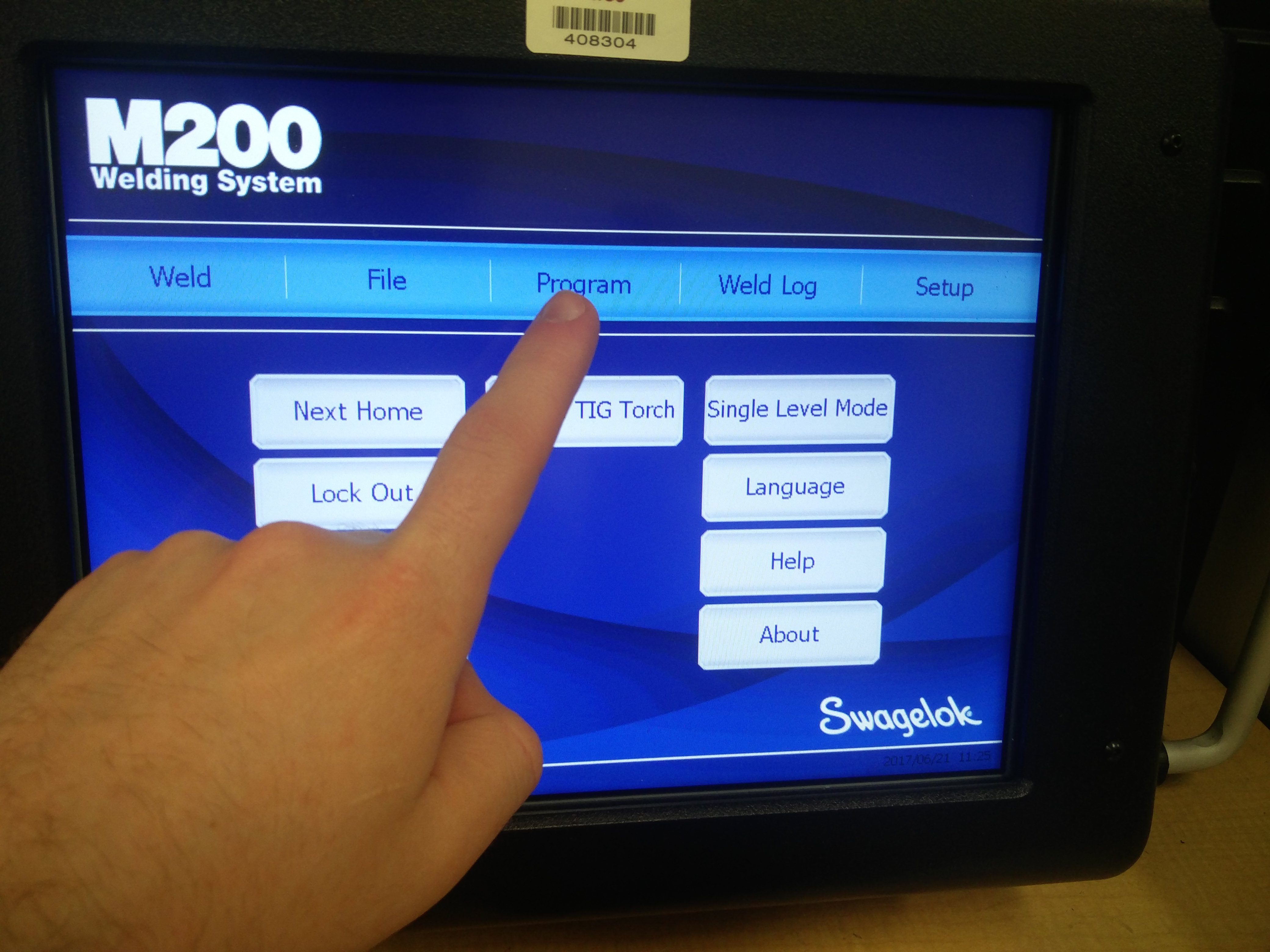
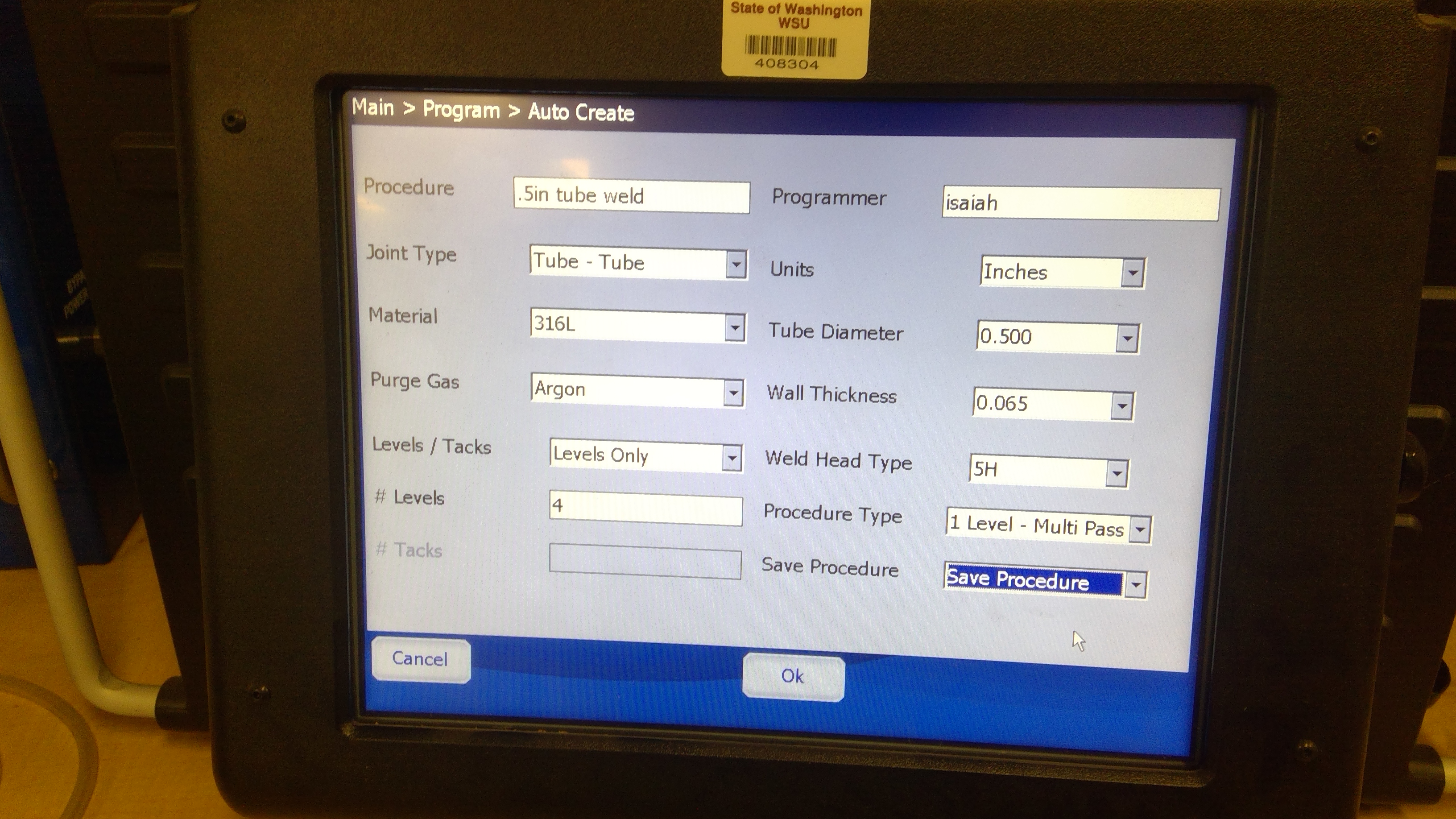
To program a new weld, begin by flipping on the machine using the on/off switch on the upper left side of the M200. Once powered on you should see a page like this. Select the “Program” key from the main menu then Auto weld and select yes to the warning.
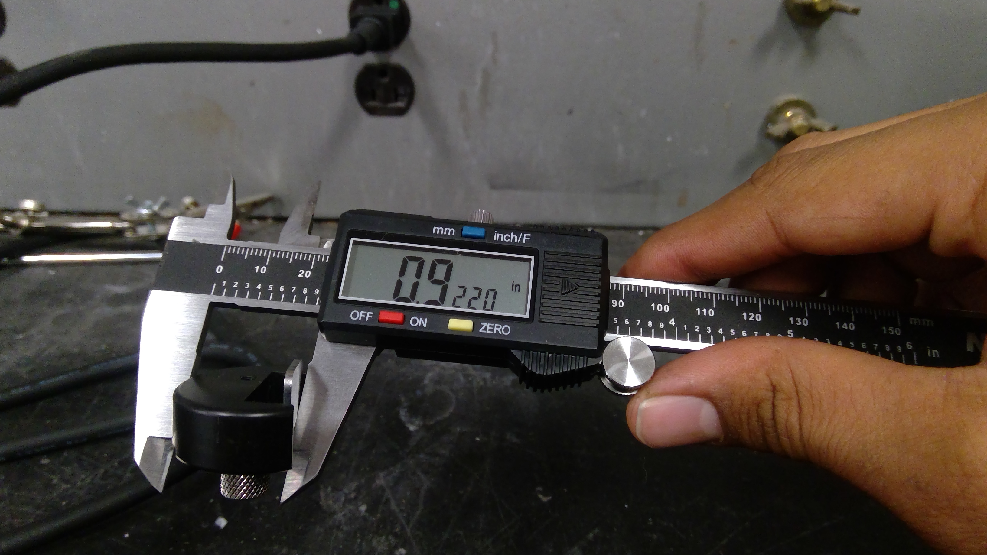
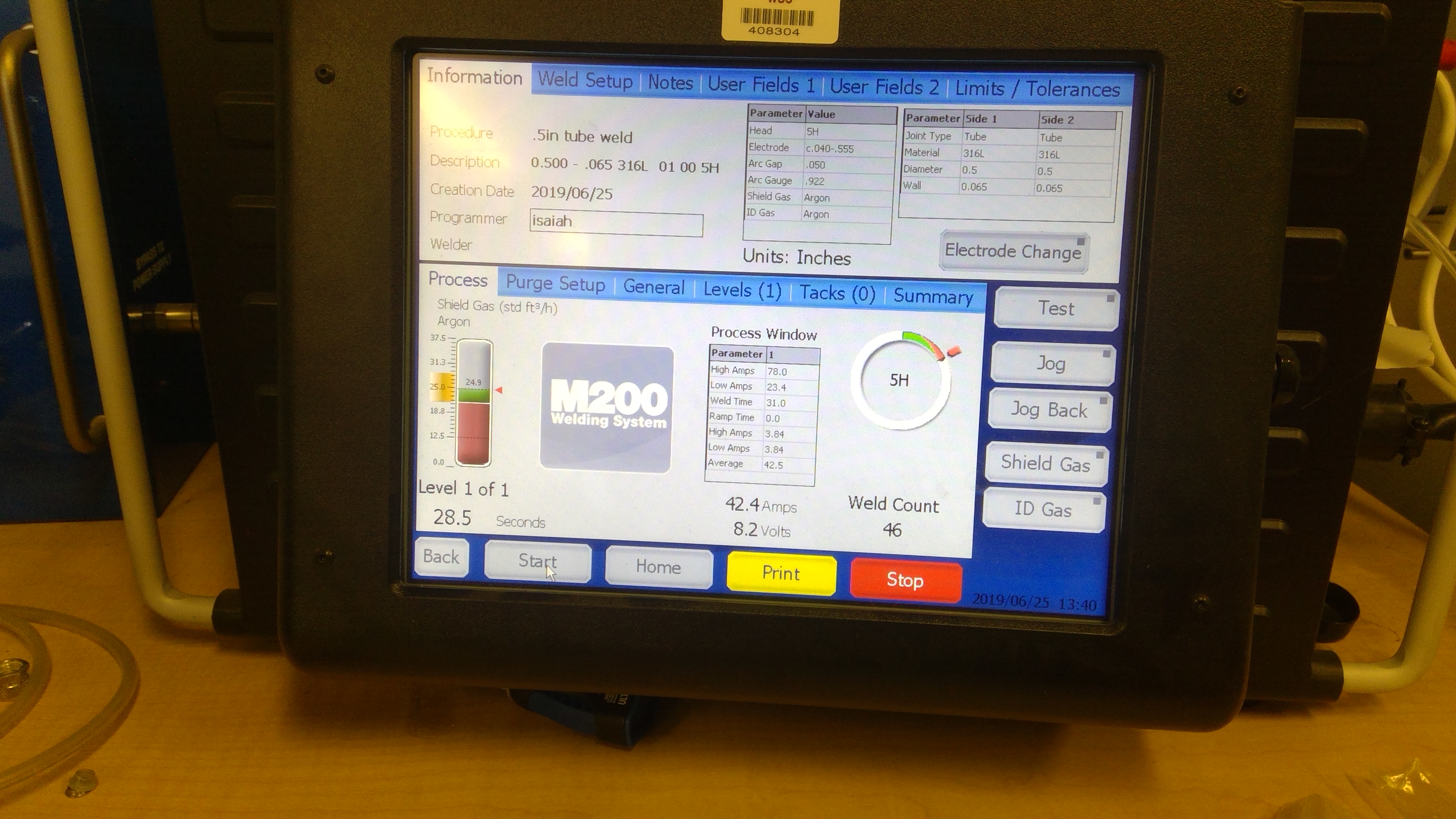
Enter the parameters as shown, You may need to use calipers to measure pipe diameter and wall thickness.
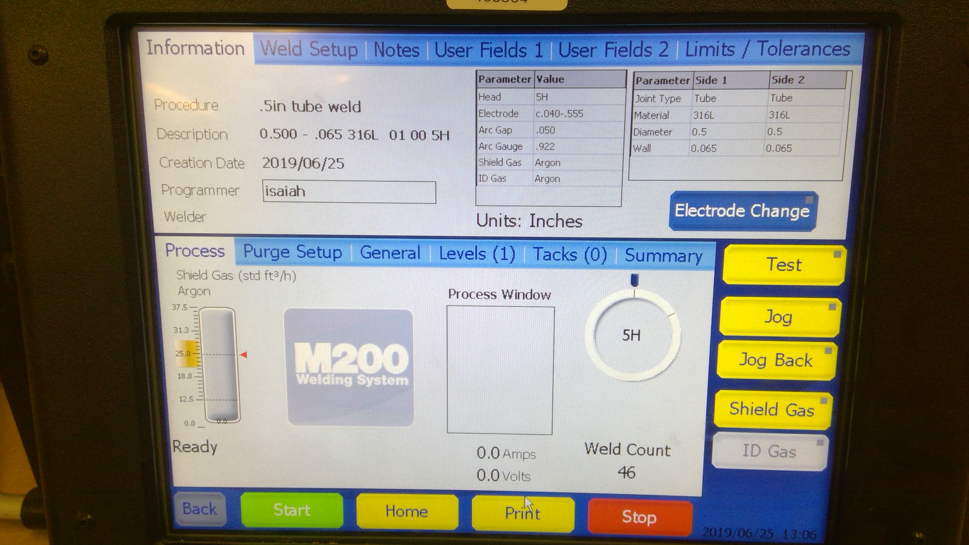
Next, once the program is entered with specific parameters the following operating screen will appear.
3.
Since the tube is 0.5 in., the Arc Gap must be set as to allow the tungsten rod to make accurate contact with the tubing. To do this, the height of the arc gauge must be set to a specific height listed in the program under arc gauge. In this case, the height is 0.922 inches.
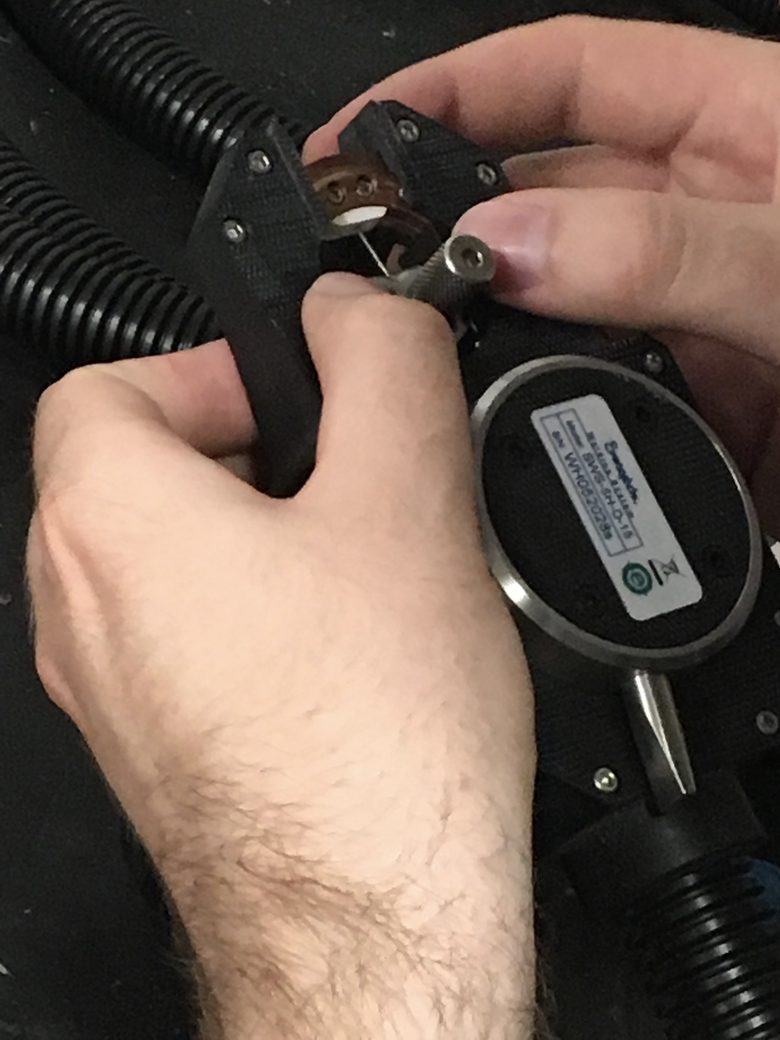
4. To insert the tungsten rod into the weld head first hit the electrode change button on the screen. This should move the electrode to the top position. Note: different weld jobs may require different types of electrodes. the process page has a table which tells you what electrode is needed for the specific job. For this case, it is electrode c.040-.555. The electrodes come in small bags that should be labeled.
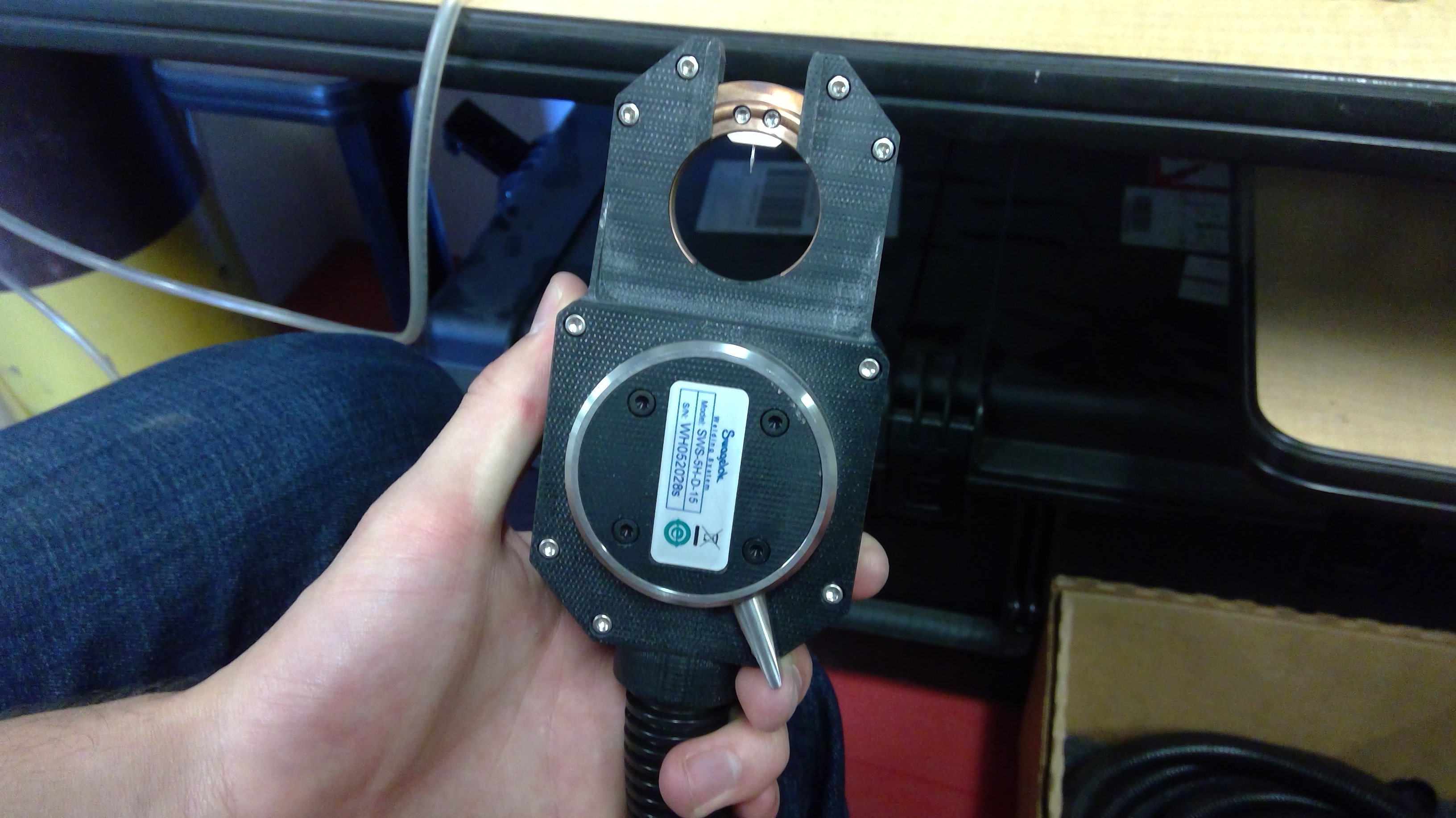
Next, place the arc gauge into the weld head where the tungsten rod is located. From there, loosen the top two bolts so that the tungsten rod can move freely. After, allow the rod to fall into the divot on the arc gauge. This will properly set the rod for welding. Finally, re-tighten the bolts and remove the gauge.
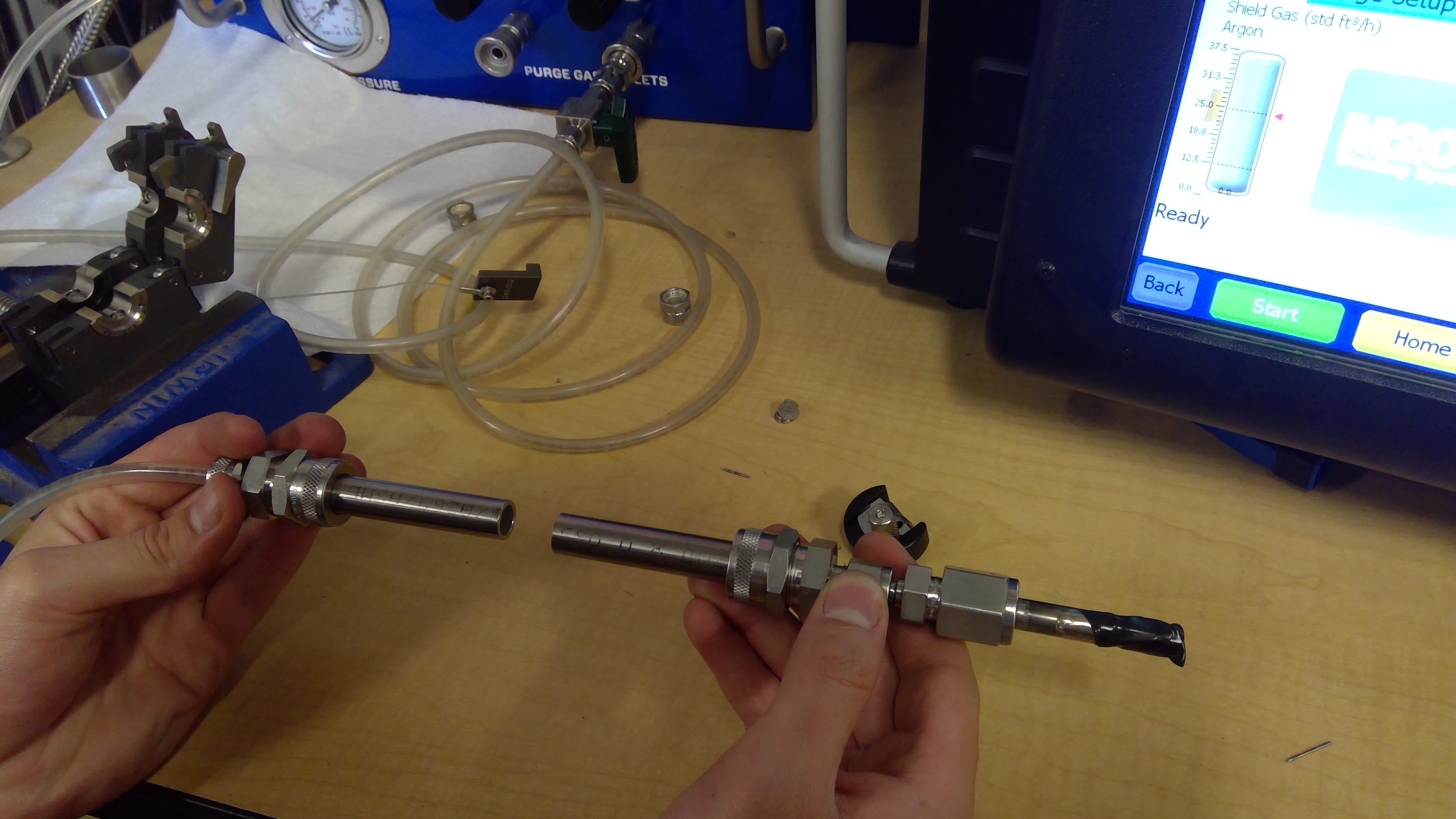
5. To prevent contamination from the air a positive pressure of argon must be flowing through the tubes while the weld is taking place. To accomplish this attach the clear tube coming from the green ball valve to the side of the tube that was not faced using a compression adaptor. To ensure back pressure, connect the other tube to the compression adapter with black tape on the end.
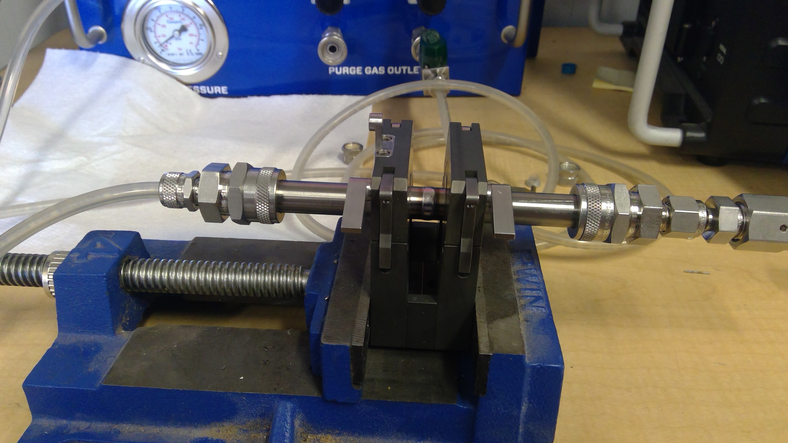
6. Now the tubes are ready to be inserted into the fixture device that holds the tubes in place.
Insert the tube connected to the valve into the left side of the clamp and use the attached spacer to ensure the tube is centered in the clamp and secure it so it does not move.
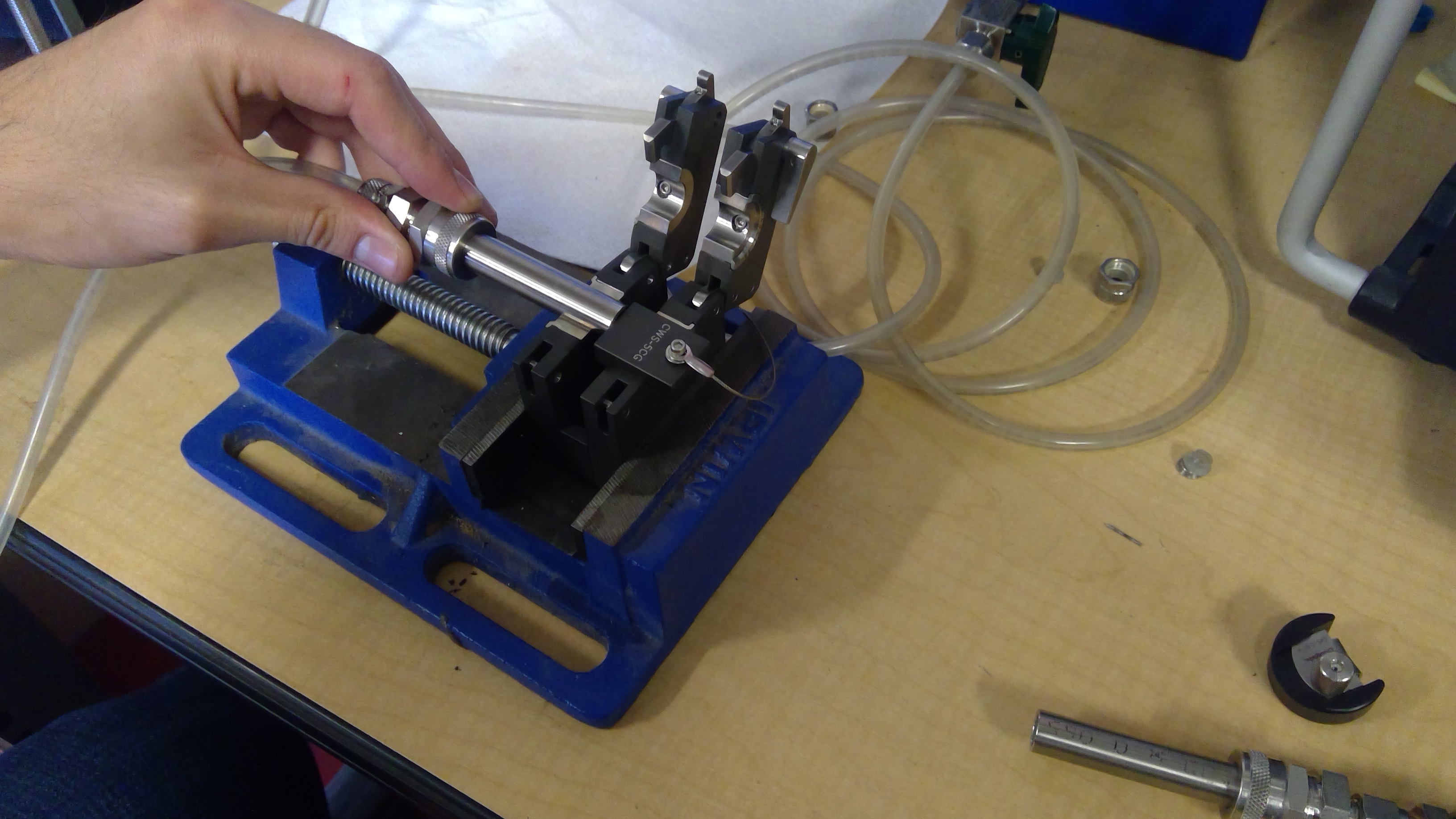
Then insert the other tube into the right side of the clamp and secure.
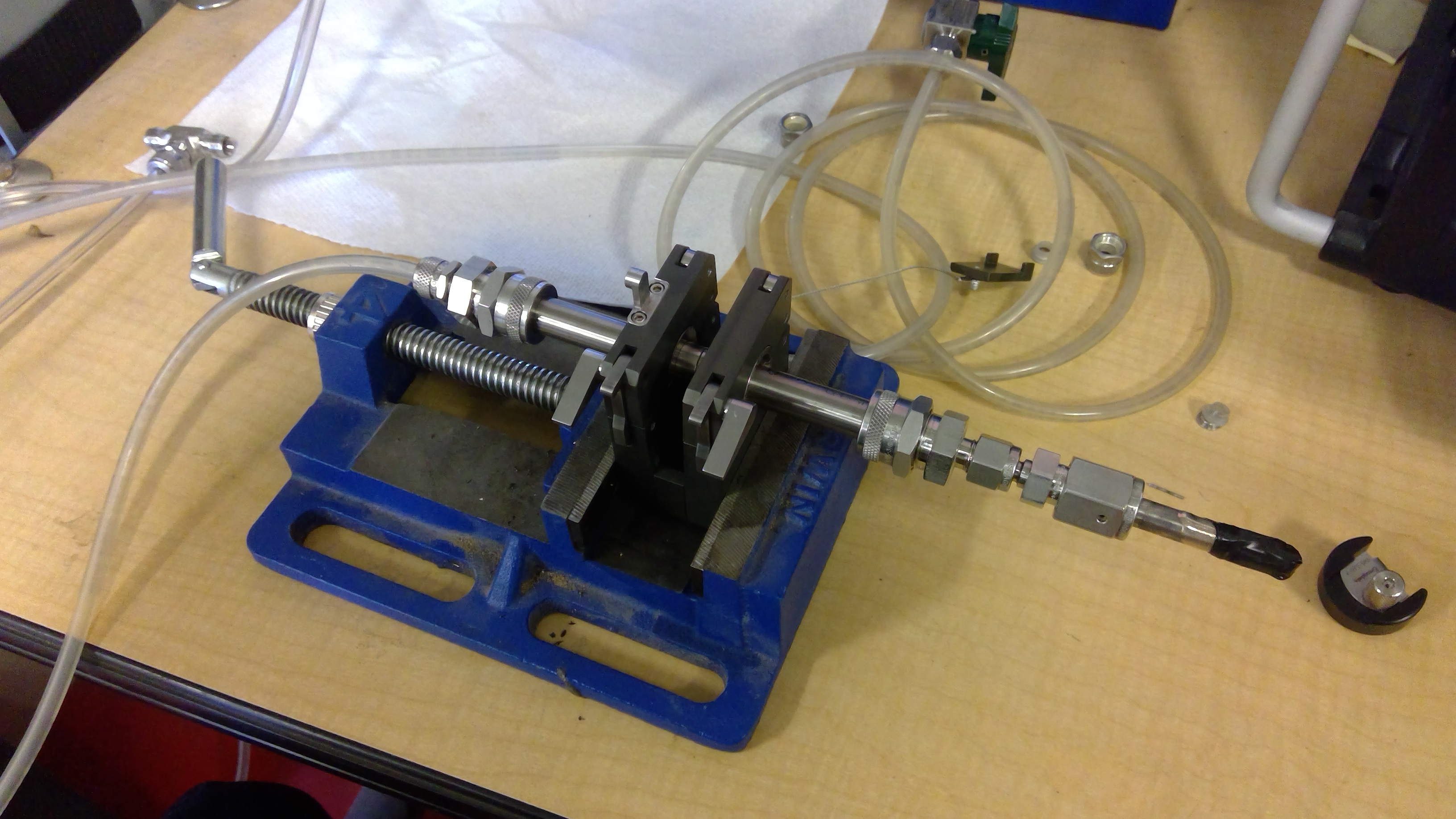
7. Finally, insert the weld held into the fixture and turn the tab on the top to secure it the clamp.
8. Now we are ready to perform the weld.
Start the weld by turning the green valve to start the flow of argon through the tubes, then hit the “Shield gas” button on the control panel to flow argon around the outside of the weld. Next hit the green “Start Button” on the bottom of the screen. The system will conduct a gas purge before welding as well as a post-purging. This ensures that there is no oxygen in the system before and after welding. The screen should look something like this.
9. Remove the weld head to inspect the weld and turn the green valve off before removing the welded tube.
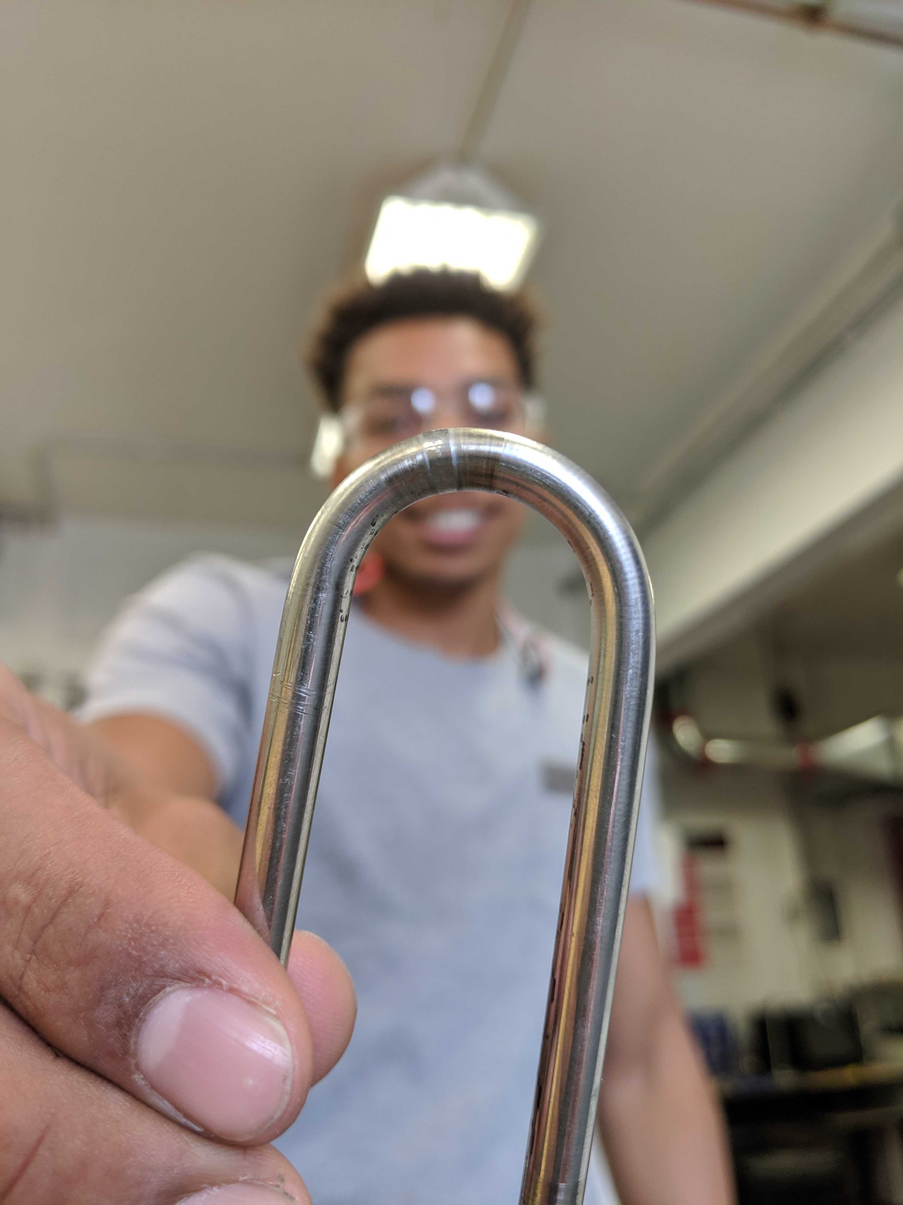
If the weld goes correctly and all pieces were set correctly, then you should have a beautiful weld as shown below. Congrats!
If you’ve done this right, the quality of the orbital TIG welds maintains the ductility of the base material and you should be able to fully bend the weld without cracking or breakage. Happy welding!