If I learned anything from my internship with Unitech Composites, it is that surface preparation is essential in all operations of composite layup and assembly. This is true for bonding as well. Surface preparations, although tedious and seemingly unimportant, are key in establishing properties that their subsequent specifications claim. To ensure that an epoxy resin can perform at a specified temperature range for a long time, adherence to the following procedure is required.
This procedure is specifically written for the application of Vishay’s M-bond 43-B, 600, and 610 adhesives in bonding strain gauges to a composite surface. These adhesive systems are a product of Vishay Precision Group Incorporated. The adhesives come in kits that provide most of the tools and materials listed below. Variation from these three adhesives or selecting a non-composite material requires a different procedure altogether. This procedure was originally written for the facilitation of bonding strain gauges to ASTM D638 Type V PA840-GSL composite samples. These samples are to be tested in CRAFT for their room and cryogenic temperature, tensile and fatigue mechanical properties.
Workshop Introduction
Tools Required:
- Work Surface
- Heat Gun
- Pencil
- Straight Edge
- Tweezers
- Precision Knife
- Small Aluminum Plate
- HSC Spring Clamp
- Soldering Iron
- Wet Rag
- Wire Strippers
Materials Required:
- PA840-GSL Test Specimen
- Isopropyl Alcohol
- GSP-1 Gauze Sponges
- Strain Gauge
- 320 Grit Silicone-Carbide Paper
- M-Prep Conditioner A
- CSP-1 Cotton Applicators
- M-Prep Neutralizer 5A
- PDT-3 Drafting Tape
- M-Bond 610 Resin
- M-Bond 610 Curing Agent
- Disposable Mixing Funnels
- Brush Caps
- MJG-2 Mylar Tape
- TFE-1 Teflon Film
- Silicone Gum Pad
- RSK Rosin Solvent
- Antimony Solder
- 326-DFV 3-Conductor Leadwire
Preliminary Operations
As a precursor to the initiation of surface preparation, be sure that all tools contacting the strain gauge, composite, or work surface are adequately cleaned with Isopropyl alcohol. In addition, rubber gloves are required for use up to the curing operations.
Before you begin, secure your work surface down with PDT-3 drafting tape. For the sake of consistency, I provided square sheets of aluminum in my workshops. The selection of a work surface is entirely up to the user; I found it easiest to maintain a small, controlled surface for ease of cleaning. Next, you are to clean the work surface by applying GC-6 Isopropyl alcohol for removing surface contamination. GSP-1 gauze sponge is then employed to remove the solvent from the surface. Be sure to wipe in single strokes from one side of your work surface to the next. Furthermore, fold the gauze with every additional stroke. Both details reduce the risk of contaminating a previously cleaned section of your work surface. Finally, it is recommended to utilize a heat gun to ensure complete solvent removal from your work surface.
Procedure
Solvent Cleaning and Abrasion
Operations 1 and 2
The first operation involves applying Isopropyl alcohol to both the strain gauge and the composite sample. You must remove your strain gauge from the mylar envelope that it comes in with a pair of tweezers and place it solder tab side up on your work surface. Reference Figure 1 for strain gauge terminology. The solder tab side will have a more defined texture and a more visible internal grid. Place your composite specimen on the work surface as well. Identical to the work surface cleaning, Isopropyl alcohol must be applied to the exposed faces of the composite and strain gauge. Attempt to wipe both components dry with one stroke of the GSP-1 gauze sponge. Do the same for your work surface if excess was applied.
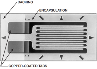 Figure 1 – Strain Gauge Components (https://micro-measurements.com/)
The second operation of surface preparation requires abrasion to remove loosely bonded coatings or contaminants. Abrade the exposed composite surface with 320-grit silicone-carbide paper until a matte finish is achieved. As a rule of thumb, a “matte finish” can be achieved with 10-12 strokes of the silicone-carbide paper. One stroke is represented by a single back-and-forth motion. To verify complete solvent removal, utilize the heat gun on the composite surface.
Between operations two and three, you have the option of applying layout lines to facilitate strain gauge placement. A pencil and straight edge should be employed in drawing crossed reference lines. These reference lines will indicate where strain measurements are to be made. These lines should also be perpendicular to one another, with one line oriented along the direction of strain. As a reference, refer to Figure 2. It is ideal to achieve adjacency between the centers of the gauge length for both the strain gauge and the composite sample. Moreover, the gauge length of the strain gauge should be as close to the gauge length of the sample as possible to capture the full range of strain within the composite sample.
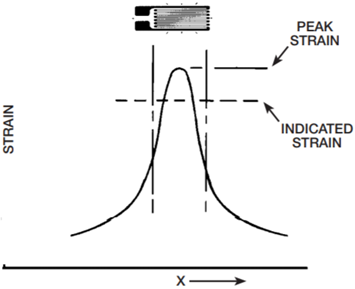
Figure 2 – Strain Measurement in Reference to Gauge Length (https://micro-measurements.com/)
Conditioning and Neutralizing
Operations 3 and 4
Operation three involves conditioning operations to both the strain gauge and the composite specimen. Conditioning serves to further clean exposed surfaces. It is recommended to heat the surface of the composite with the heat gun to promote proper conditioner effect. Apply M-Prep conditioner A to the surface of the composite and the strain gauge with a CSP-1 cotton applicator. Continue conditioner application until the cotton applicators are no longer discolored. Be sure to keep the surface of the composite constantly wet with conditioner during the application of M-Prep conditioner A. Remove the remaining conditioner with a single stroke of GSP-1 gauze prior to evaporation. It should be noted that this operation should be completed as quickly as possible to limit conditioner absorption into the composite.
Operation four is identical to operation three, but with neutralizer 5A instead of conditioner. Neutralization ensures that the surface alkalinity is brought to a 7.0 to 7.5 pH. This is preferred for all strain gauges produced by Micro-Measurements. Like the application of the conditioner, the application of the neutralizer should be performed as swiftly as possible to limit neutralizer absorption into the composite. This completes surface preparation operations.
Cutting and Adhesive Prep
Operations 5 and 6
In the first series of workshops, we purchased too big of strain gauges. Although our strain gauge grid width was identical to the width of the gauge section of our specimens, the matrix width caused overhang. Refer to Figure 3 for strain gauge dimensional callouts. Therefore, strain gauges with small matrix widths will be utilized in the future. However, cutting off the backing material was necessary for the first series of workshops to limit overhang. To trim these samples, the only main restriction was this: a minimum of 5-mil clearance between the cut and the internal components of the strain gauge must be maintained. If a cut came within 5 mil of the pattern or solder tabs, the user would risk the application of residual stresses that could skew the results obtained from the strain gauge. You will notice that there are triangles and angled dashes around the perimeter of the strain gauge pattern and solder terminals in Figure 1. These are indicative of this 5-mil dimension. If a portion of these shapes remains visible post-cutting operation, the cut is outside of this 5-mil threshold. To perform the cuts, PDT-3 drafting tape was employed in holding the samples taught during cutting of the backing material. Also, Exacto-knives were used for the physical cutting of the strain gauges themselves.
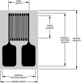
Figure 3 – Strain Gauge Dimension Callouts (https://micro-measurements.com/)
Next, the adhesive may be prepared for application. It should be noted that mixing and curing operations may vary depending on the selected adhesive. These instructions will be based on the M-Bond 610 resin. Ensure that the adhesive and subsequent curing agent are at room temperature during mixing operations. Utilize a provided plastic funnel to empty the contents of the curing agent bottle into the adhesive bottle. Then, tighten a brush cap to the adhesive bottle and proceed to shake for 10 seconds. Mark the bottle with the date mixed for pot life record keeping. Allow to stand for (1) hour at room temperature prior to its application.
To position the strain gauge for eventual bonding, place a short length of MJG-2 mylar tape down over half of the gauge tabs and the entire terminals. Peel the tape back at a shallow angle (about 30˚) to remove the strain gauge with it. Transfer the tape-gauge assembly to the composite sample. If layout lines were applied line the strain gauge with the layout lines. Otherwise, center the gauge lengths of the strain gauge and specimen. Also, try to center the grid width about the gauge section width of the specimen. For consistency, establish a consistent solder tab side of the sample.
Adhesive Application and Cure Prep
Operations 7 and 8
The seventh step involves the application of the mixed adhesive. First, peel back the tape and place the exposed end of the tape behind itself as if to manually create double-sided tape. The strain gauge bonding surface should be exposed. At this point, apply a thin layer of M-Bond 610 adhesive to the exposed strain gauge face with the brush tip. Do not allow the brush applicator to touch the tape mastic. Allow the adhesive to air dry for 5 to 30 minutes at 75˚F and 50% relative humidity. Place the strain gauge back down into position. Apply firm hand pressure to the area of the strain gauge. While holding the uncovered half of the strain gauge down, peel the tape back, leaving the strain gauge on the sample gauge length.
To prepare the sample for curing operations, a clamping force of 30 to 40 psi must be applied. To do this, spring clamps were provided in the adhesive kit. These clamps maintained a nominal application pressure. To achieve the 30 to 40 psi application force, silicone gum pad and aluminum sheet were cut to an area that would ensure 30 to 40 psi clamp force regardless of the two different spring clamp options. To eliminate contamination to the strain gauge, a piece of TFE-1 Teflon film is first laid over the strain gauge. Then, the precut silicone gum pad areas are placed over the strain gauge and the parallel face on the other side of the composite sample. Finally, the precut aluminum areas are placed over both silicone gum pad areas. The clamps are placed on the sample and you are ready for curing.
Curing and Soldering
Operations 9 and 10
The clamped samples are then placed in an oven.
The prescribed cure recipe is as follows:
- Raise the oven from room temperature to 325˚F at a rate between 5˚F/min and 20˚F/min.
- The samples must remain at 325˚F for a minimum of 2 hours.
- Upon the completion of this 2-hour duration, the samples must be cooled to 100˚F before their removal from the oven. The clamps, aluminum, silicone gum pad, and Teflon are then removed.
Be sure to consider the melting temperature of your composite matrix material. If this prescribed cure recipe, exceeds or is relatively close to the melting temperature of your matrix, the geometry or properties of your sample may be altered and lead to inaccurate results. To cure per this recipe, the oven in the basement of TFRB was programmed with the above cure requirements.
The last operation in bonding a strain gauge to your sample is the soldering operations. It is recommended to use the provided RSK rosin solvent to remove residual mastic and other contamination prior to soldering. This solvent can be blotted dry with the GSP-1 gauze sponge after application.
As depicted in Figure 4, leadwire is then soldered to the strain gauge soldering terminals. The white and black wires are soldered to a single tab while the red wire may be soldered to the other. To perform the soldering operation, leadwire, a soldering iron, solder, a wet rag, and wire strippers are all required. Lastly, a protective coating may be applied to the strain gauge and solder terminals to protect them from wear. Allow the protective coating to air dry before continuing.
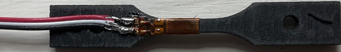
Figure 4 – Finished Product
Closing
I would like to thank my colleagues, Nathaniel Swets and Drew Boettner for their efforts in video editing and recording respectively. With their help, I was able to provide the contents of my workshop to those online. Furthermore, I would like to thank all of those who were able to attend a workshop in person to both learn the process and facilitate sample preparation. All of the operations detailed herein were transcribed from in-depth analysis of the adhesive specification, strain gauge specification, composite specification, and Vishay bonding procedures. As you can tell, specification analysis has become something I thoroughly enjoy performing as a means of constructing procedural guidelines. If you have any feedback or questions in relation to the procedures above, feel free to get in contact. Thank you for reading!