MLI Basics
The Multi-Layer Insulation (MLI) Shield (aka thermal radiation blanket) is very important in cryogenic systems. MLI shields insulate components from thermal energy transferred via light on rockets, satellites, and cryogenic experiments. The shield consists of 10s of alternating layers of polymer mesh and reflective mylar (metalized nylon) film. For a 2.5cm (1″) thick blanket at 1×10^-4 torr vacuum level, equivalent R values of ~1440 can be obtained (Technifab). Typical insulation of a building wall is in the equivalent R of 10-60 (Energy.gov). It’s no wonder engineers in the Linde Devision of Union Carbide named it “superinsulation” in the 1950s (McIntosh). To understand how MLI blankets work, consider an equation approximating the resistance to radiative heat transfer:
R_rad= 1/(A_s σϵ4(T_s^2+T_sur^2)(T_s^2+T_sur))
where As = radiating surface area, σ = Stefan-Boltzmann constant, ϵ= emissivity, Ts = the absolute surface temperature, Tsur = absolute surroundings temperature. Or more generally: q” = σϵ(T_sur^4-T_s^4) assuming the surface is at lower temperature than the surroundings. The knobs available to turn in this equation are the area of the radiation, emissivity or absorptivity (want these to be near 0 (shiny, reflective) to create large resistance), and the temperature of the inner MLI shield should be low which can then limit the amount of heat needed to be lifted from the MLI shield structure to maintain low inner shield temperatures. The other knob to turn is the total number of layers of the blanket. MLI shields minimize heat transfer by 1) stacking up many layers (32<#<64) of these MLI mirrors to blunt radiative heat transfer, 2) isolating the layers from each other via contact resistances to the polymer scrim, and then 3) placing the MLI shield in a high vacuum (<0.001 Pa) to remove molecules that could conduct heat via convection. While that may sound simple enough, the practical realities are quite challenging of making these MLI shields in reliable, low-cost, and effective ways. There’s a very good reason NASA still maintains teams of MLI blanket professionals for any mission.
Professional vs Photo-film MLI Test Comparison
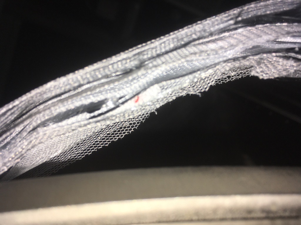
Materials needed for this type of insulation depend on the application. Some of the more costly items can be replaced by more commonly used and accessible items. Joanns (yes the nationwide fabric store) sells 100% polyester mosquito netting which is essentially the same PET material and weave pattern as Dacron netting used in industry. The aluminized mylar layer can be purchased as a photo-film from most online retail outlets as a single layer roll. One key difference is that professional MLI is often metalized on both sides to maintain the high reflectivity and low absorptivity of the aluminum. However, most low-cost photo-films are often metalized on only one side. You can use a multi-meter to measure the resistance on either side of the film to make sure you have the right (metal) side facing outwards in your shield.
For many years we were concerned about the very low cost of this photo-film mylar compared to the professional grade gold-coated mylars. It could be that the photo-film is reflective in the visible light spectrum that we see, but transparent in the infrared band that transfers most thermal radiation. To attempt to resolve this issue we used a 160 W light bulb and an infrared thermal imaging camera to compare professional grade MLI materials we received as a sample to the photo-films, based on the number of layers in a stack. Figure 1 below shows the thermal images based on the number of layers.
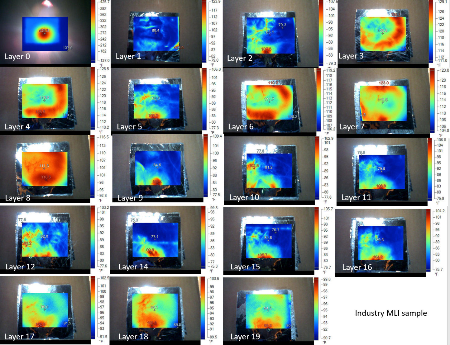
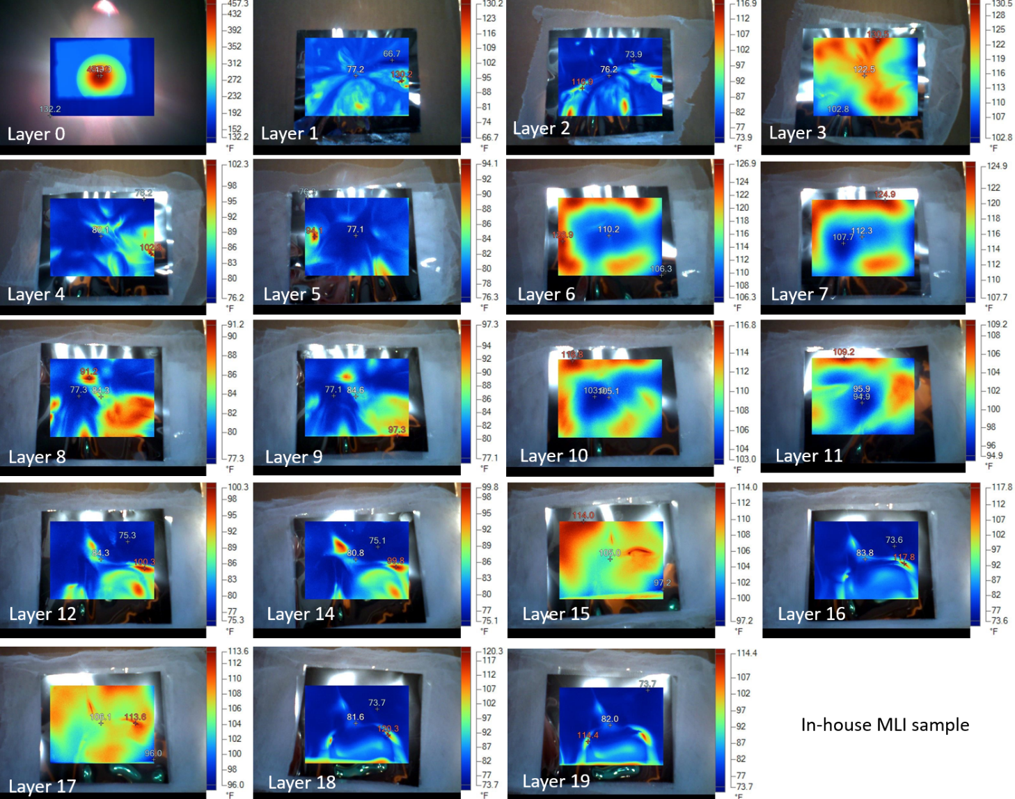
Figure 2: Industry MLI sample (top, blue line on plot) vs in-house MLI sample (bottom, orange line on plot) from 0 layers to 19 layers. Note: A sequential vertical orientation was used to align 160W light bulb, samples, and FLIR infrared camera. This testing was not done in a vacuum chamber or at cryogenic temperatures however performance is comparable in similar conditions.
As you can see, after only a few layers of the stack we cannot see a significant difference between materials with the thermal imaging camera. This could change at cryogenic temperatures or in a vacuum where the problem is more sensitive to material challenges. So if you have active cooling and have margin where a simple basic blanket will suffice, you’re probably fine making your own with lower grade materials.
How to make an MLI shield for cryogenics
The shield is external in nature given the localized cryogenic area needed to be shielded from radiative heat leak. This usually needs to be removed to access components within. This drives design to be modular and easily placed/removed. Given the need to cool the inner layer of the shield, the shield starts with a polished aluminum or copper inner wrap that faces the cryogenic components and is thermally anchored to a cryocooler. The choice between the two (aluminum or copper), and thickness thereof, is a tradeoff between thermal mass and diffusivity. Although a heavier shield will lead to lower thermal resistance, a higher thermal mass will take longer to cool down. Normally this thickness is dependent on whether the shield has an internal structural frame by which the thin aluminum wrap is fastened mechanically and thermally to or the material is thick enough to support itself.
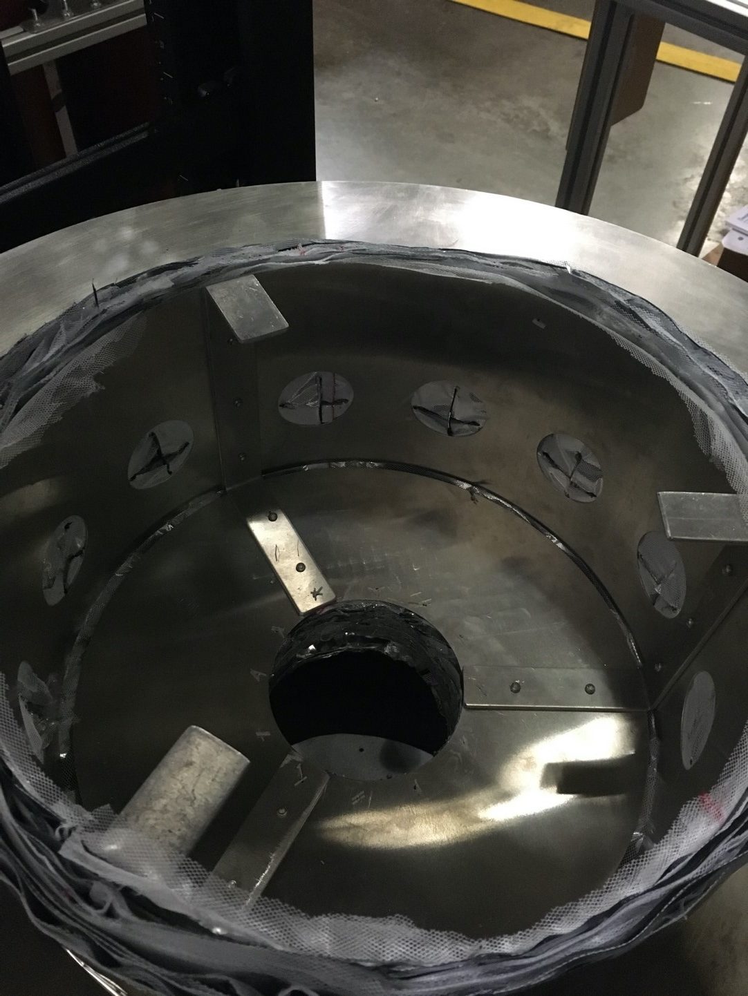
In the most recent shield made for CHEF a two part design paradigm was chosen to minimize thermal mass while maximizing modularity seen in figure 2. Often, the shape paradigm of an MLI blanket is decided by the shape of the surrounding vacuum chamber and to maximize the workable volume within. Since CHEF is a cylindrical vacuum chamber where the top cylinder rises for access, the MLI blanket is most easily made in two parts where the top cylinder rises off of the working area and the bottom cylinder remains static in the chamber while making changes.
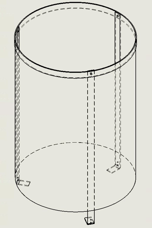
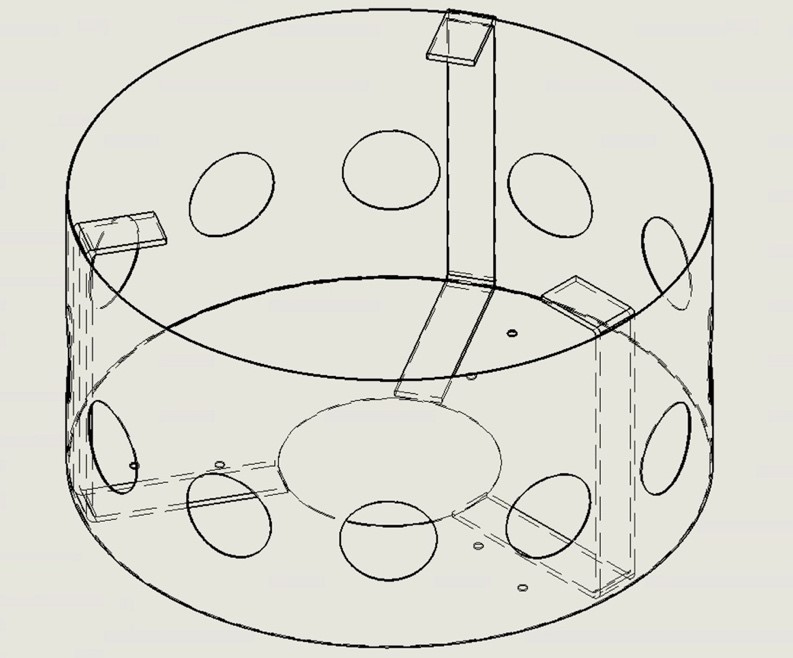 Figure 3: (Top) Upper MLI shield frame designed for ease of removal. (Bottom) Lower MLI shield frame with passthroughs.
The aluminum frame supports the MLI shield both within CHEF and when the shield is taken out for changes. It’s easy to forget the necessity of maintaining the structural integrity of the shield when removed from the cryostat. You want the shield to remain intact to minimize chances for rippage and tearing during frequent installs. In the CHEF case, the frame is made from two aluminum hoops, three aluminum legs, and a sheet of aluminum that wraps around the outside. There is also a top cap that has been welded to the top. It’s necessary to thermally anchor all parts of the shield and support structure, otherwise they will take considerable time to cool just due to thermal radiation.
After a structural frame is constructed, work may begin on the actual layers of the MLI shield. The following procedure goes through the process of how this newest MLI shield was made for CHEF. The layers consist of a layer of mesh to eliminate conductive heat leak between individual mylar layers. This pattern must be thought out to minimize number of seams while snuggly conforming to geometry. The bolt of mesh was laid out on a work table and wrapped around the frame to enclose the cylinder. There was a slight overlap of approximately half of an inch. This mesh was then cut as seen in figure 3. (Notice that I’m wearing gloves — fingerprint oils are not very reflective and are easy to trace back to the perpetrator.)
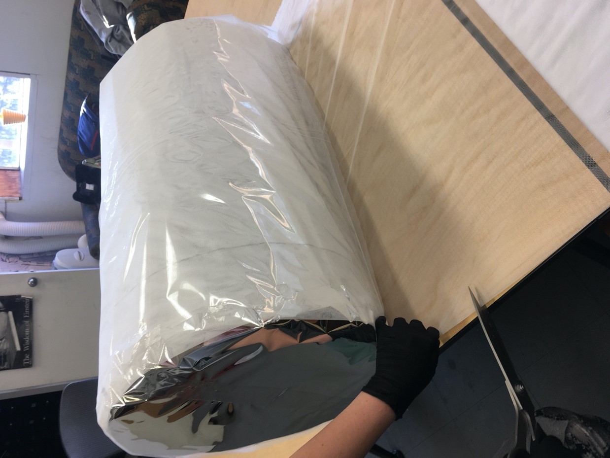 Figure 4: Measuring and trimming the mesh to fit around the shield.
The mesh comes doubled up on the bolt. Because of this, two layers of mesh were cut at a time. The second piece of material was set aside for the next mesh layer. Next, more mesh was laid out. The frame was carefully laid down so that the circle of the cap could be marked on the mesh.
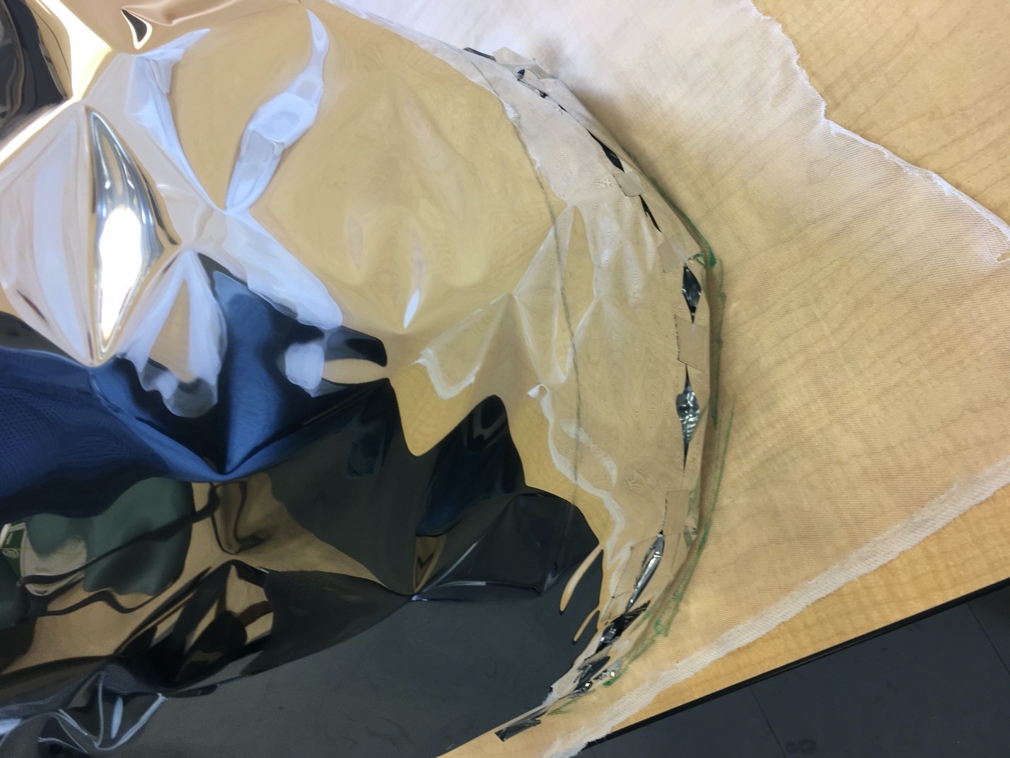 Figure 5: Marking out the circle to sew on to the top of the shield.
The frame was set aside. The mesh circle was cut out with an allowance of approximately a quarter of an inch. This was done with unfolded mesh so only one circle was made at a time.
Now that the pieces had been cut, it was time to sew. First, the circle was attached to the rectangle that would become the cylinder. The circle was put on top of the rectangle. The long edge of the rectangle was even with the edge of the circle. The circle sat approximately a quarter of an inch in on the rectangle. These were placed on a sewing machine. They were lined up with the quarter inch seam line. They were carefully sewn in a circle, pulling the material fairly tight as it went along to that it would not bunch up as seen in figure 5.
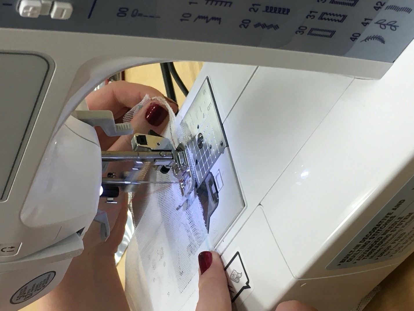 Figure 6: Proper tension on the mesh when sewing is important to keep the shield the right size.
At the beginning and end of the seam, backstitching was done so that the seam would not pull itself out. Once that seam was completed, the two short edges of the rectangle were still loose. They were lined up. Again, they were placed on the quarter inch seam marker on the machine. Here, a straight seam was sewn. Again, backstitching was done at the beginning and end. Next, the completed piece was flipped so that the seam was on the inside. It was carefully fitted over the top of the frame. If the fit was satisfactory, the excess would be trimmed as seen in figure 6.
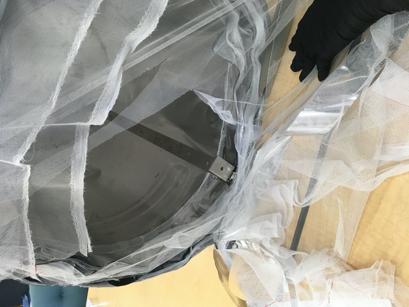 Figure 7: Trimming down a few layers that were too long.
Then, the next aluminized mylar layer can begin. Each layer is made slightly larger than the one before it, so don’t try to cut corners by making 5 or 10 layers at a time. The construction of an MLI shield requires patience, precision, care, and careful planning. One must take care to not accidentally introduce foreign contaminants onto the material. The seams should not be aligned within the shield. The layers cannot be too tight or too loose to maintain the optimal layer density. Reflective mylar tape is used to bridge the seams on the mylar layer, 1/4″ or 1/2″ thickness should be fine depending on your precision. Make sure to have a nice tape dispenser handy has it’s incredibly difficult to use tape while holding a blanket layer, while using gloves. Mylar film is incredibly easy to tear, so you want to leave as few stress concentration points as possible while cutting. It is not necessary to completely seal the entire seam as small openings (that light cannot transfer through) allow gas molecules to escape during evacuation and improve the shield performance.
The cutting process worked much the same as with the mesh as seen in figure 7.
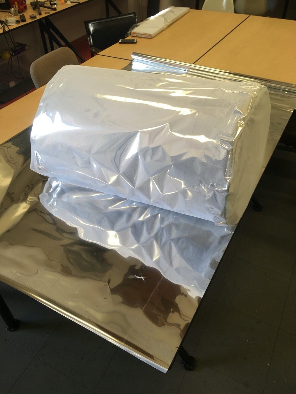 Figure 8: Measuring and cutting the mylar.
However, the mylar is not doubled up. Instead, the rectangle for the cylinder would be cut. Then, the excess would be trimmed off. The circle for the top would be cut out of that excess. Ensuring that the metal side of the mylar is facing out (to reflect radiative heat transfer going from hot to cold), wrap it around the mesh layer. This was easier if one person was holding the mylar and the other was taping. It would be pulled tight but not too tight. Usually, it would look sort of like dragon scales with slight deformation when it was near or just too snug as seen in figure 8.
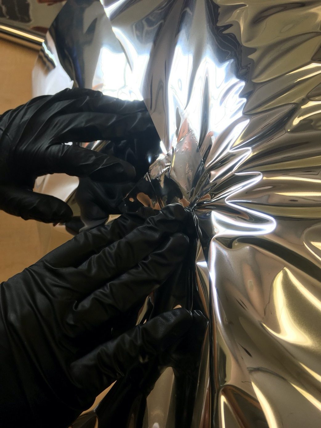 Figure 9: Securing the mylar with mylar tape.
Once the sides were taped, but not completely covered in tape, the mylar cap would go on. It would be held over the end. Four points, 90 degrees apart, would be taped to the cylinder. Then the rest would be taped down at enough intervals to ensure it was covered. At this point a mesh layer is complete as shown in figure 10. 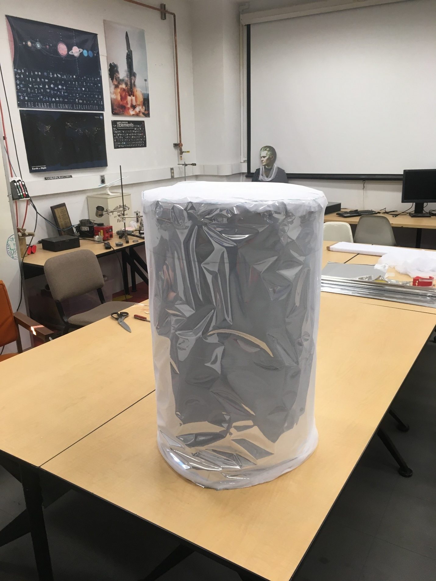
Figure 10: A completed mesh layer.
A mesh and aluminized mylar layer constitute a layer of MLI shield. There is a range of acceptable amount of layers depending on temperature level and layer number/density. Johnson investigated the optimal layer density here. The investigation yielded an optimal layer density as shown in figure 11. With the upper and lower MLI shield on CHEF a layer density of 14.0 (layer/cm) and 16.8 (layer/cm) were achieved respectively. Ideal densities for 20K cold temperature insulation would be 9-10 layer/cm for the Modified Lockheed Equation (MLE) and 14 layer/cm for the Lockheed Equation.
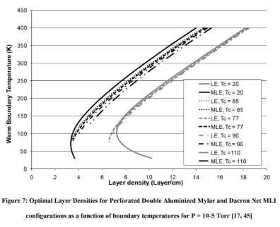
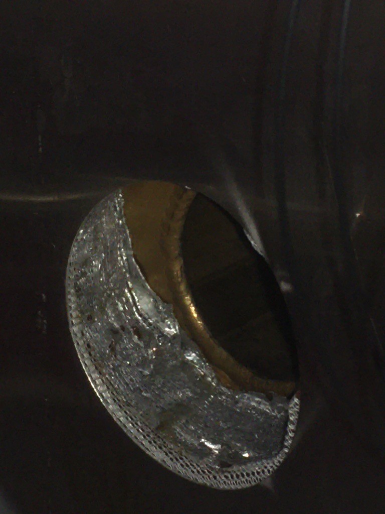
Figure 11: (Top) Optimal MLI layer density form Johnson (2010) for double (perforated) aluminized mylar. (Bottom) Lower CHEF MLI shield layer view into KF-40 port.
These steps would be repeated several times. Every few layers, approximately five, a tagger (used for installing price tags to clothing with nylon leaders) will be punched through the latest layers to keep them all together. As layers build up, additional trimming is needed. This process is repeated until the MLI shield is at least 32 layers. Whereas as mentioned above 32 total mesh layers and 32 total aluminized mylar layers are stacked on top of each other.
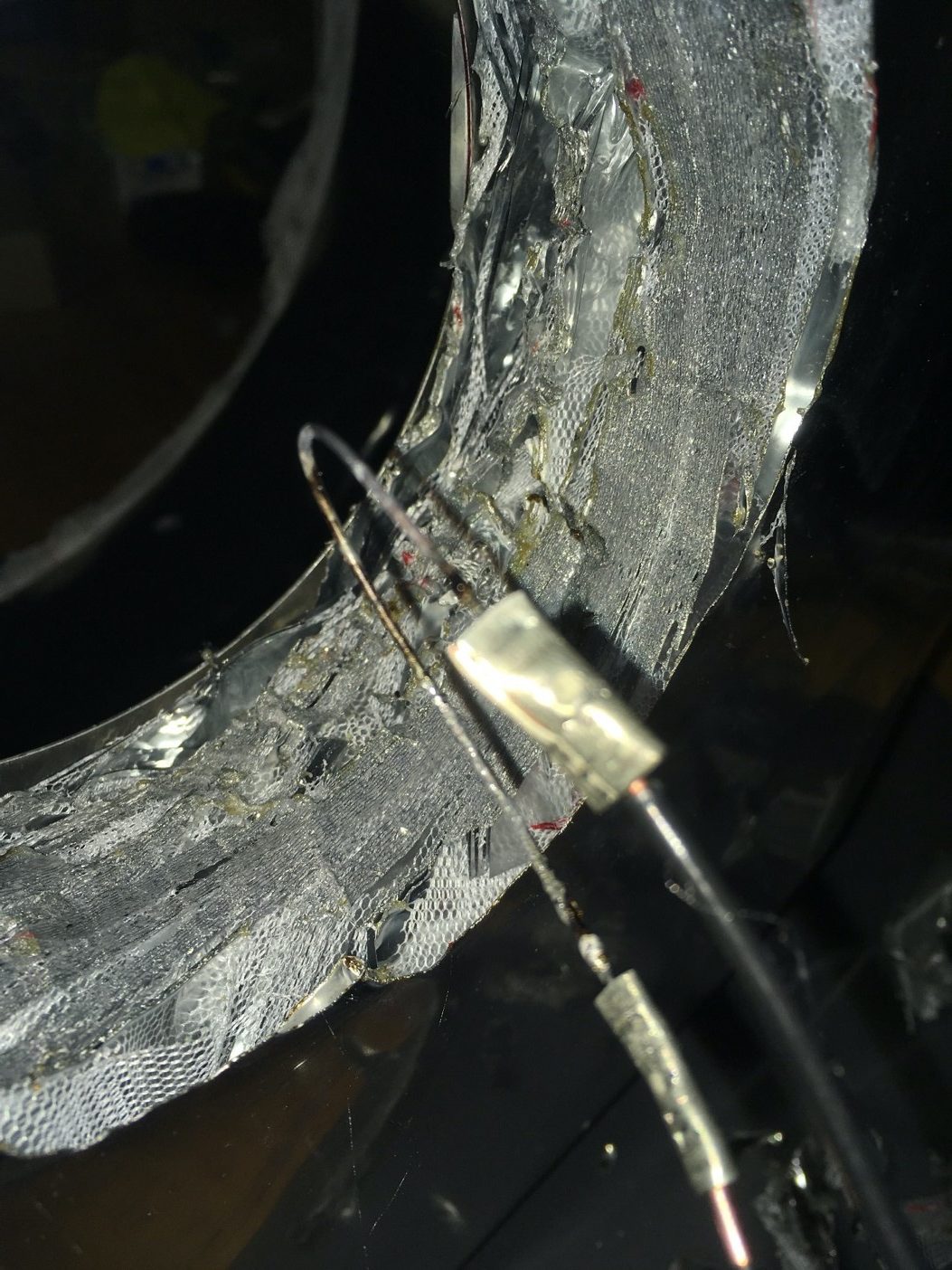
This same process is repeated for the lower shield as well. However, for the lower shield, pass through holes had to be put into the shield to accommodate wires and tubing. It is rather difficult to cut through 64 layers of material at one time with conventional cutting tools. To accomplish this, a hot wire cutter was created. This was done using a variable power supply, electrical wire, and stainless steel 316 wire. The stainless steel was wired to create a handheld cutting tool. It was then used to cut out clean holes and slits that were necessary for the wires, cryocooler heads, and tubing to pass through in a well ventilated area (fume hood).
Yet the key to a MLI shield is its placement into a high vacuum environment as seen in Figure 2.4 from Ekin or figures 24 and 25 of Johnson (2010).
Care was required not to “short circuit” the blanket at the transitions between the two blanket halves. If the inner part of one shield has a view factor (can see) the outer part of the other shield, thermal radiation will transfer directly between the two and “short circuit” the entire stack. The same happens with sloppy pass through seams that allow thermal radiation to transfer directly from the vacuum chamber wall to the test specimen. Finally, care must also be made to only allow cold components inside of the MLI shield. A hot component inside the MLI shield also “short circuits” the blanket. Efforts to lighten and improve attachment of MLI to tanks has been taken with discrete spacers that eliminate the need for scrim layers seen in Kopelove (2016).
Finally, anchoring the blanket into place is important. If you can use turnbuckles or other clasps on the structure, great. However, we’ve found that garbage bag wire ties or pipe cleaners are great for anchoring in a reusable way while minimizing thermal conduction.
Now your MLI shield is finished! We’ve found our MLI shields last for many years and repeated installations. This CHEF MLI shield will hopefully last the longest yet.
References:
Technifab Products Inc, “Cryogenic Insulation”, https://technifab.com/cryogenic-insulation/
Department of Energy, “Insulation”, https://www.energy.gov/energysaver/weatherize/insulation
McIntosh, G E, McIntosh, R C, (2019) “Evolution of Cryogenic Engineering”, CEC 2019 invited paper
Ekin, J. (2006) “Experimental Techniques for Low-Temperature Measurements”, https://www.researchmeasurements.com
Johnson, W. (2010) “Thermal Performance of Cryogenic Multilayer Insulation as Various Layer Spacings”, https://stars.library.ucf.edu/etd/1622/
Keller, C. W., Cunnington, G. R., et al., (1974) “Thermal Performance of Multi-layer Insulations, Final Report, Contract NAS3-14377, Lockheed Missile and Space Company, Sunnyvale, CA, https://ntrs.nasa.gov/archive/nasa/casi.ntrs.nasa.gov/19740014451.pdf
Kopelove, A. (2016) “Next Generation Multilayer Insulation with Discrete Spacer Technology, Parts 1 and 2”, https://cryogenicsociety.org/34885/news/next_generation_multilayer_insulation_with_discrete_spacer_technology/
Other resources:
An episode of the NASA podcast Curious Universe also has some information on the MLI blankets used on spacecraft: https://www.nasa.gov/mediacast/sewing-for-spaceflight