Plumbing manifolds on a cryogenic system are just as essential for functionality as proper electrical wiring from a simple light switch to an overhead light. Just like a wire sends current from point A to point B, a plumbing manifold can send hydrogen, helium, nitrogen, and other gasses from point A to B. The number of complex functions performed by plumbing manifolds leads to complexity that approaches integrated circuit boards. However, much less information, not to mention engineering standards, are available on how to reliably construct custom plumbing manifolds for research purposes. This post overviews the systems we have developed at HYPER for academic research experiments, ensuring your cryogenic plumbing manifolds are made right the first time, and hopefully the last time too.
It is essential manifolds be laid out and built properly for multiple reasons:
- Manifolds can be transporting flammable or even noxious gasses so leaks must be minimized for personnel and lab safety.
- Various valves have different purposes such as reducing, halting, or switching direction of flow. It is vital to have valves in their proper orientation and properly fixtured to mitigate improper flow, unwarranted pressure buildup, or mixing of gasses.
- Manifolds are expensive. Components can be costly to replace; including valves ($54- $250 per valve), union components ($8- $200 per fitting), regulators and gauges (up to $1K per component), and the tubing running through the system (fluctuating in cost but averaging around $3.20 per foot for a stainless steel alloy). Depending on the number of components, a full manifold can cost over $10,000 for just the aforementioned.
The WSU HYPER Lab is no stranger to designing and building plumbing manifolds. Each system including CCC, CRAFT, CHEF, ORF, and Titan have a plumbing manifold designed and built for their specific operating needs. Over time, as lab members have designed and built manifolds of their own, they have learned tips and tricks along the way to make the best functioning and most attractive manifolds in an efficient manner.
Designing your manifold
If you are dealing with cryogenic and/or hydrogen gases. You should have a corresponding safety plan because the amount of energy/power involved could hurt you very badly. The AIChE Center for Hydrogen Safety (CHS) (of which we are a founding member) has a wealth of safety planning and trainings to get you started. Our own safety planning process is described here. An essential part of this safety planning process is development of a Plumbing and Instrumentation Diagram (P&ID). Like any good circuit diagram, a good P&ID takes some time but pays off in the end.
Start developing your P&ID with pencil and a paper. Consider the following:
- Where is my working fluid/gas coming into my experiment from (the source)? Are you filling directly from a gas bottle or after the gas has already passed through a regulator in the bottle closet?
- What has to happen to the fluid before being utilized by my experiment? E.g. pressure control, mass control, volume flow control, purity control, temperature control, etc.
- What instruments do I need to verify that my controls are performing as expected? Will these instruments continue to work in emergency situations like a power outage, when I most need to know the status?
- What valves, tubing, and fittings are required to control and relieve the flow when necessary? Will I be able to valve off (and purge) frequent interconnects like to gas bottles or leak detector ports? Are these valves and fittings rated for the temperatures and pressures that could be experienced within the system? Note that soft copper, aluminum, and thin wall tubing cannot handle a full 3000 psi from a standard gas bottle. Keep in mind that hydrogen embrittles many materials and cryogenic fluids can flow in tubing outside of a cryostat in atypical situations — make sure your components are compatible.
- Do all pressure/cryogenic vessels have a dedicated pressure relief device that passively vents to a safe/approved location? Keep in mind that even tubing (if large) can accumulate considerable fluid power (V*deltaP). If it can accumulate more fluid power than a conventional air compressor hose, it needs a dedicated pressure relief valve. If your system vents hydrogen, it needs to vent into a dedicated hydrogen vent stack (see CGA G-5.5). Keep in mind that many gases can displace oxygen. If you are venting a large amount of cryogen, it needs to be into a space that will not displace too much oxygen.
- Have you done 1-5 above with the minimum number of interconnects possible? Every interconnect is a potential for another leak. Every component left off the system costs nothing, weighs nothing, never leaks, and never breaks. Iterate your sketch to get to the minimum.
- Have your sketch reviewed by someone with experience. You will likely find opportunities or things you missed and be able to fix them before moving your sketch over to a computer aided drafting (CAD) software. You will eventually have this drawing reviewed by a team when you conduct your HAZOP.
Once you have completed the list above, do a nice drawing in CAD, many of the standard programs of P&ID systems. To make it official, Our library has a copy of the ANSI/ISA 2009 Instrumentation Symbols and Identification standard. A briefer version is available on the P&ID Wikipedia page. Remember you need to have a full HAZOP review of your system before you order your parts.
Building your manifold
Once your preliminary plans are reviewed with your HAZOP and approved, you can begin building your manifold. The primary focus of this section will be on methods of building out the board, components, and tubing for the manifold.
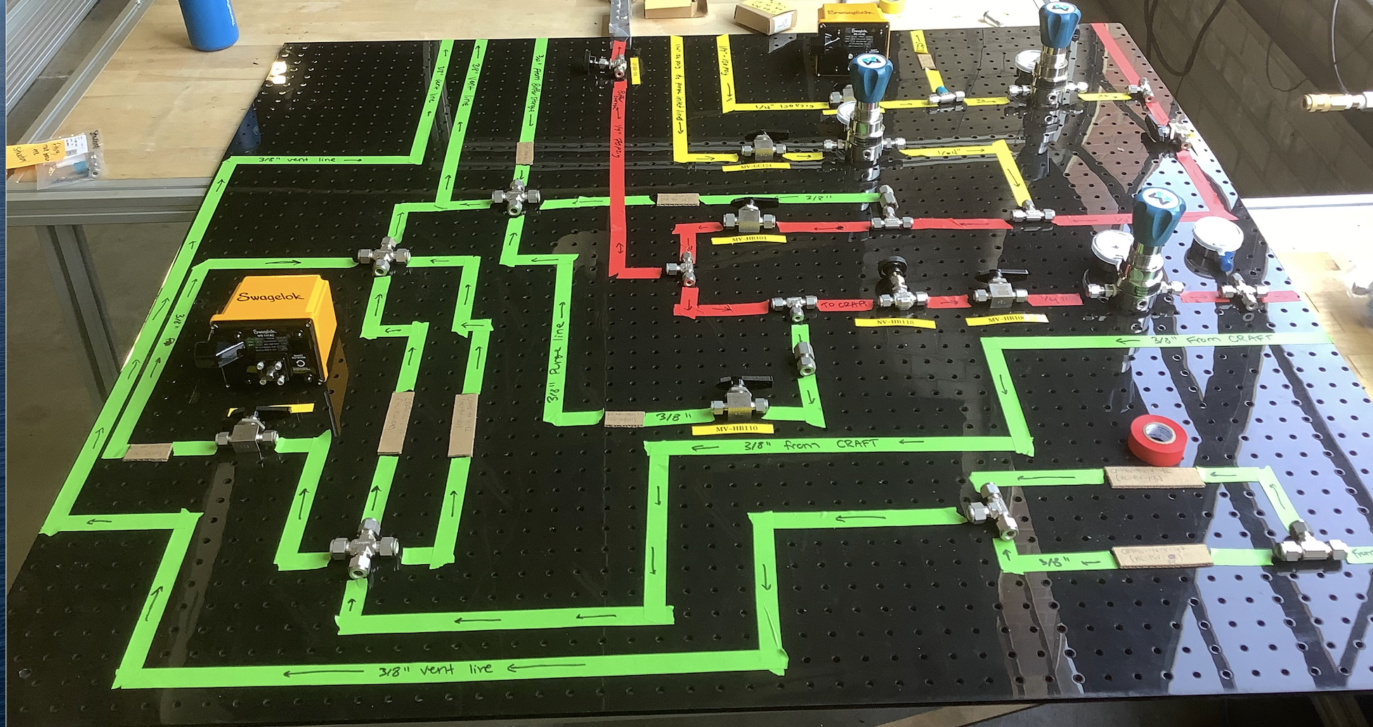
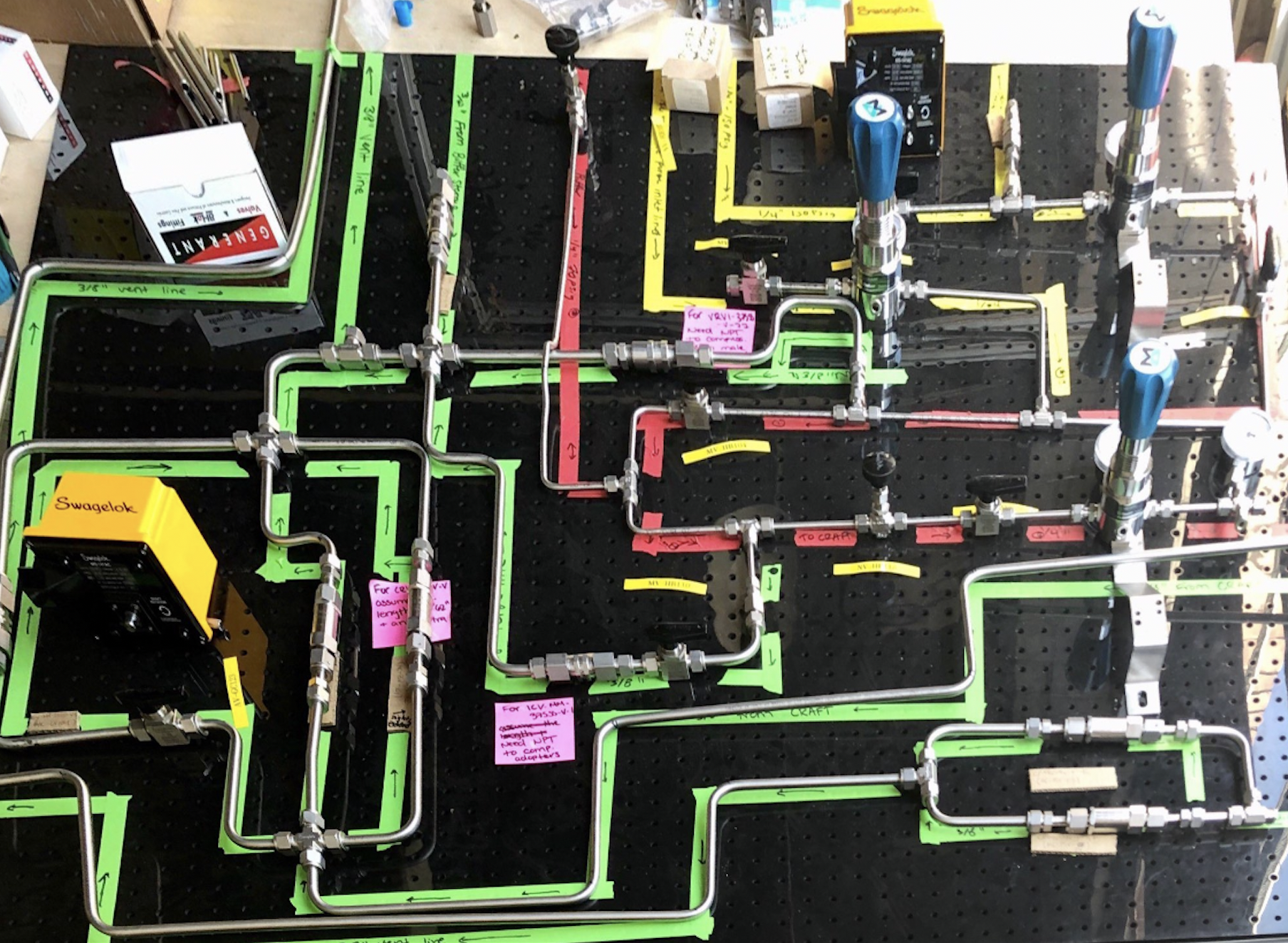
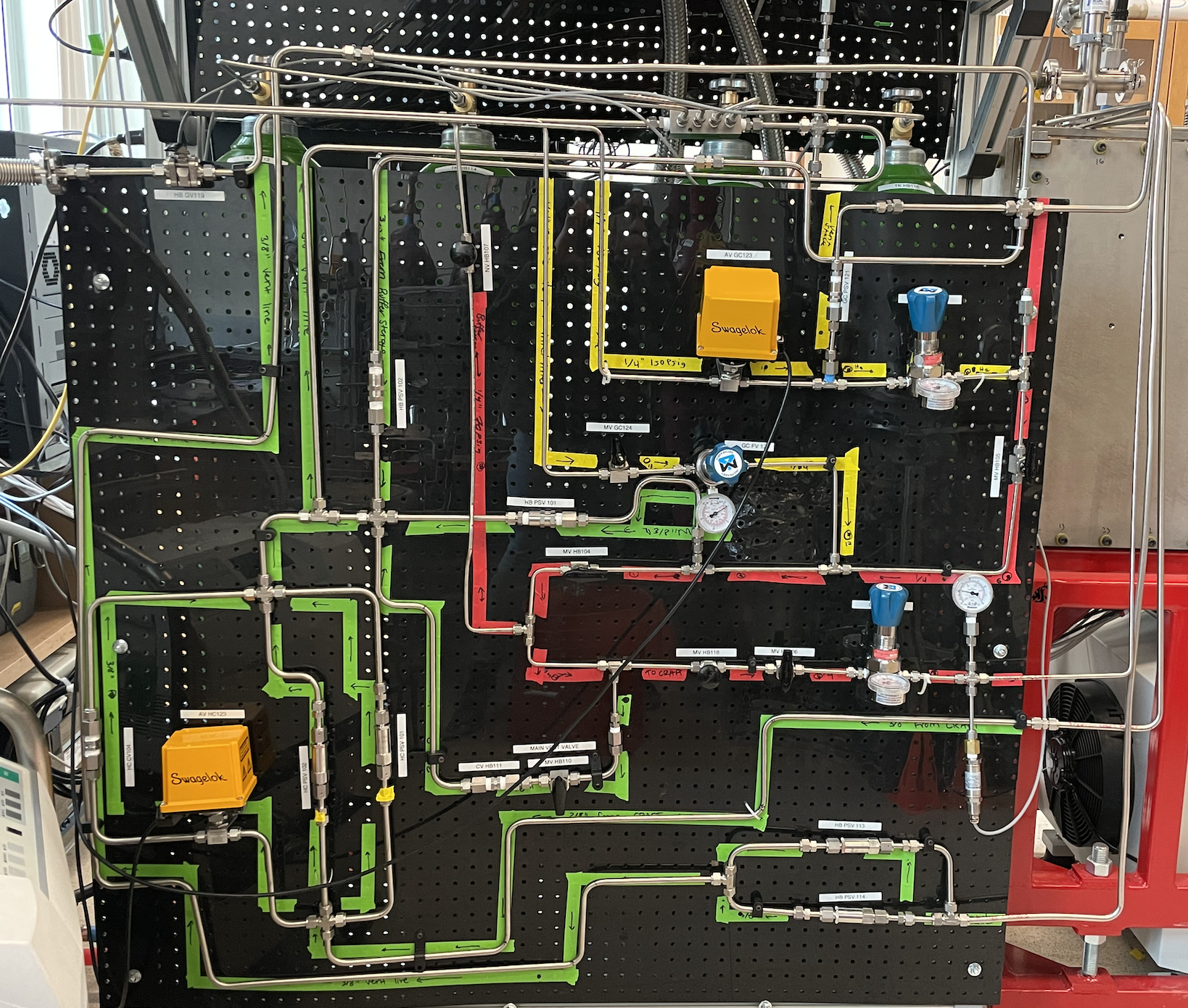
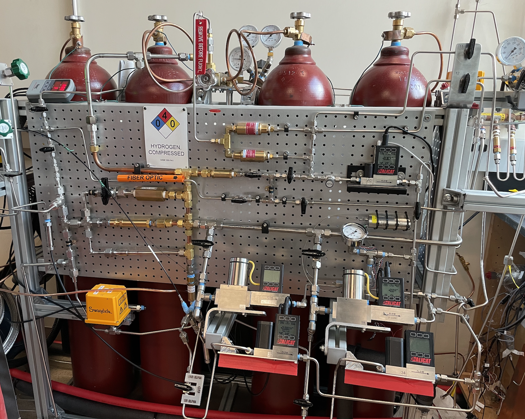
The board, kind of like the motherboard of a computer, is the foundation for your manifold and needs to be taken seriously. We use either aluminum or stainless steel pegboard to ensure the board doesn’t melt in a fire. The holes in the pegboard allow for components to be moved, fixtured, and wires to pass from one side of the board to another. We like to put plumbing on one side and wiring on the other. To get started, layout your board on one of the manufacturing tables and begin to place your components on the board similar to where they are placed in you P&ID. When modeling on CAD, try to play it conservatively in spacing out the board. It is easier to have room to branch out than it is to have to condense. As a general rule for layout, it is best to have it structured by sections. The primary sections typically include:
- Inlet line for gases going into the system
- Process lines for instrumentation and controls
- Outlet/vent/purge line for gasses going out of the system to the vent stack
- Vacuum line which allows you to vacuum down the internal system and manifold
When structuring a manifold, it is helpful to reduce the amount of overlap with lines. Try to centralize each type of line in its own respective region if possible. The sections can be color-coded by placing colored tape on the base of the board. This will help with operations and allow for a more user-friendly interface. Taping your manifold out also helps in reducing the amount of build error, time, and components (so money) when building a manifold since it can act as a guide for cuts and bends.
Adding the fittings
With your color coded tape on the board, it is time to start placing your tubing and associated fittings on the board. HYPER uses many types of fittings, the most common are swaged compression fittings, Vacuum Coupling Radiation (VCR), National-Pipe-Tapered (NPT), orbital-tig-welded, indium gasket joints, and vacuum Kwik-Flanges (KF). Nearly all of our room temperature gas manifolds consist of swaged compression fittings, NPT, and orbital-tig-welded connections. The others are for cryogenic and vacuum use, which is a separate discussion.
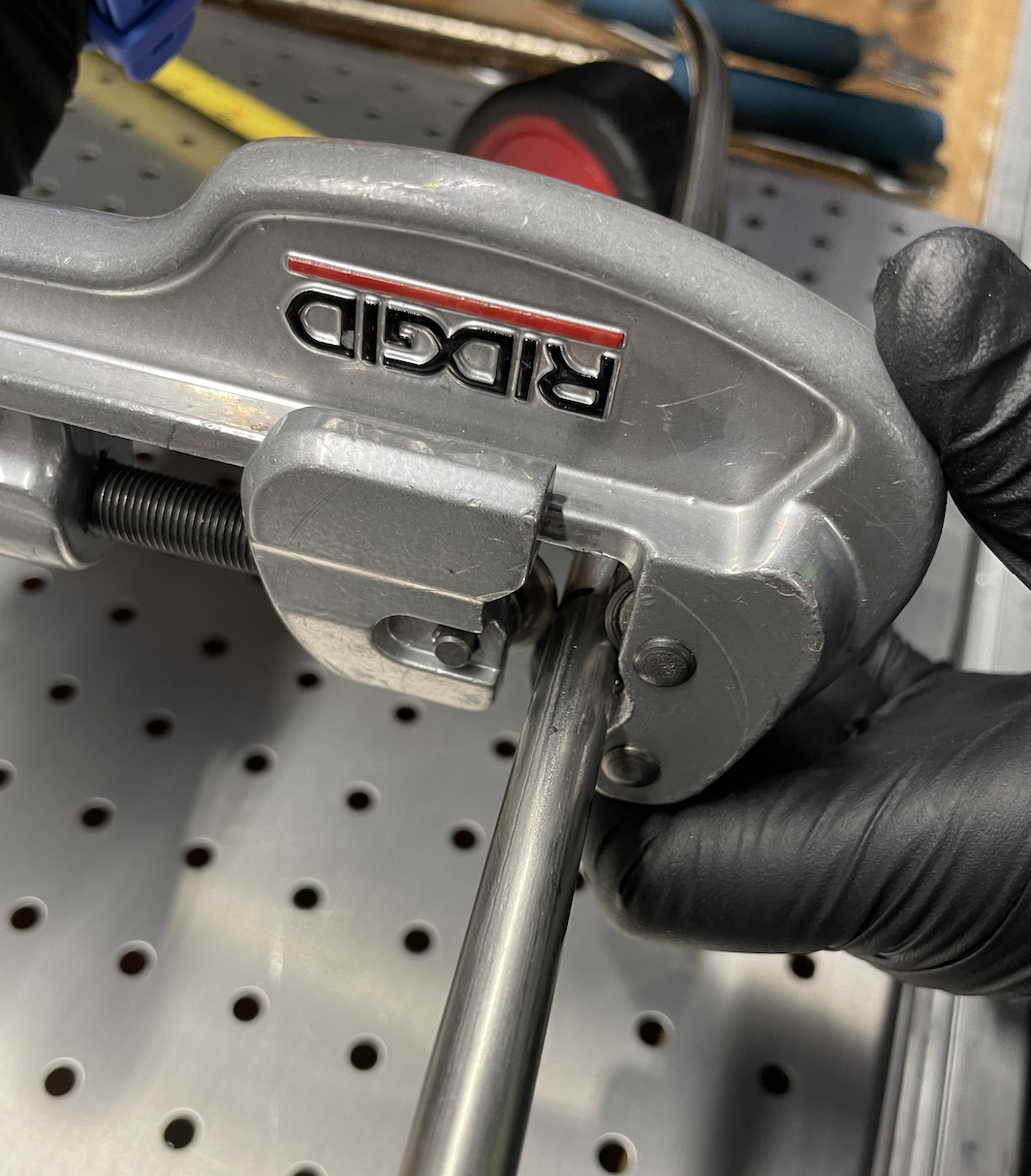
“Swaging” is a common term used as a verb to describe the process of permanently joining three pieces of metal together specifically used for compression fittings. Compression fittings allow a permanent seal while still permitting easy access to take on and off pieces of line in a manifold. The process of swaging has five main components:
- The line, of varying sizes, that will be transporting the gas across a system.
- The back ferrule
- The front ferrule
- The nut
- The body bevel
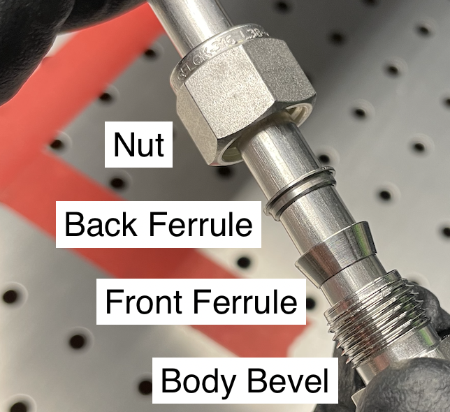
It is important to note that the tubing to be swaged must be softer than the ferrule material (e.g., use brass with copper, stainless only with stainless). You should not use brass, copper, and stainless steel fittings interchangeably due to the variations and hardness which can result in an inadequate seal formation. Using the appropriately sized wrench, it is possible to compress (or swage) the back and front ferrule around the line using the nut. This creates a permanent seal around the tubing and then when tightened inside the nut, creates a compression seal with the nut. It is critical to install these ferrules to ensure all of the pieces are there and in the correct order. Set up a jig so that it cannot be done wrong and then inspect.
Swaging the ferrules is permanent to the line and can not be redone unless you completely redo the line. But the fitting itself is reusable and makes taking off sections of line much easier. Refer to the Swagelok’s installer’s guide for a more in-depth tube fitting guide beyond this article.
Another handy tip is to make loops in your tubing that act as springs — these springs easily bend to prevent torque on the fitting itself from adjustment or thermal contraction which can result in leaks. These springs also allow a fitting to be easily cut off and replaced with enough bend in the spring to reuse a line. The tubing approaching your fitting should be straight and parallel with the fitting for several inches to ensure alignment of the front ferrule — misalignment is one of the most common swaged fitting leaks.
Be sure to use the swaged fitting gauge tool and following the torque guides when installing swaged fittings. Mark the fitting with a line extending across both sides of the fitting once you have done it correctly. When done correctly, swaged compression fittings can be reusable over the lifetime of the experiment.
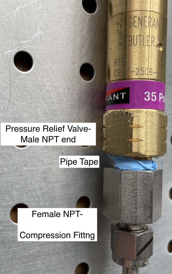
The second most common type of fitting used in the lab’s plumbing manifolds are NPT fittings. These consist of a male and female counterpart with a threaded insert where pipe tape is added and tightened with a wrench. This is another method of joining components such as pressure relief valves which commonly have a male NPT on each end so must be joined with a female NPT to compression fitting.
The teflon tape application is almost always where NPT fittings leak. For a 1/4″ NPT fitting we use the following steps:
- Make sure the male and female NPT fittings are clean such that any prior teflon tape has been removed.
- Get a teflon tape wide enough to cover the entire thread length of a male fitting (1/2″ width is usually fine for 1/4 NPT).
- Wrap the tape tightly around through threads. The direction of wrappings should be clockwise when looking at the end of a right hand thread to ensure the tag end of the tape is held down against the other tape when tightening.
- Use at least 5 wraps (you will need more for larger NPT fittings).
- Pull the tape to break it.
- Use your fingernail to press the tape to the bottom of the thread and rotate the fitting such that your fingernail follows the thread to the base of the fitting. This ensures that there is not a gap for gas to leak from the base of the thread.
When tightening the male NPT fitting into the female fitting, make sure that the female does not have a sharp edge or bur that grabs the tape and pulls it from the base of the thread. Hand tight with a wrench is fine, just make sure you have spaced the fittings far enough apart for any rotating valve handles or gauges to clear other parts of the manifold.
Measuring, Cutting, and Bending the tubing
When starting to build the manifold, it is a good rule to start in one corner and work your way across the board doing one size of line. Then once that is all complete, work across the board with the other sizes of line. If there are overlaps, start with the line that is underneath since that line will be straight through and the overlaying line will need to be bent in order to fit nicely over the first line.
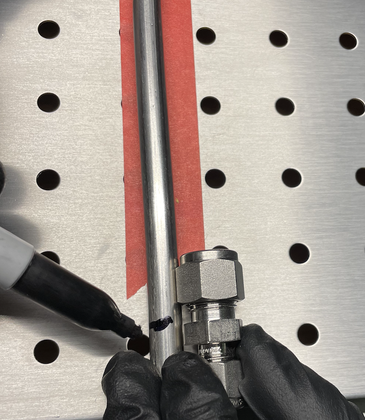
Starting in one corner, measure for the first cut of line from one shoulder of a tube fitting to the other. If there are bends, measure along the bends as well. Once you have a measurement, if it is a short piece of line, and straight, add about 1/4” so that you have a little of excess that you can later cut.
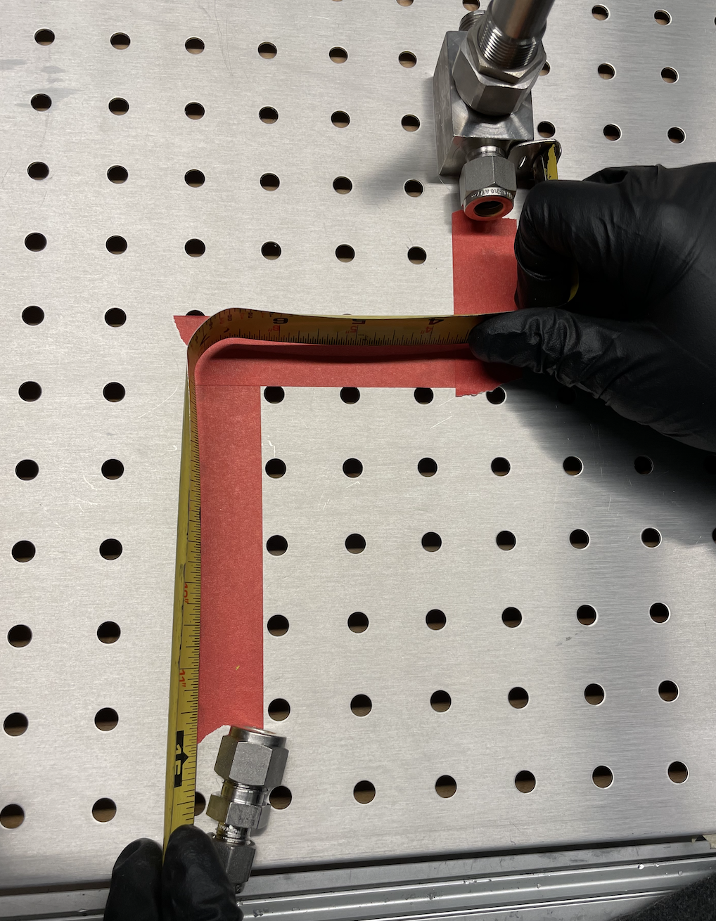
It is always good to overestimate and cut down than underestimate and have to completely redo the cut and waste line. This is also a reason you should order extra line. The amount of line you add for excess should also increase depending on how long the total section from one fitting is to the other. It should also increase depending on how many bends there are. to account for bend radii. So if you have a single run of line that is 110” with 7 bends, you would want to cut a chunk of line with even up to 5 inches of excess to account for bend radii.
Once you have the measurement, take the line, measure it, and mark with sharpie where the desired cut will be. Taking a tube cutter, place the line between the roller and blade of tube cutter. Align blade with inside of marked line.
Holding the line in place, start tightening the handle of the tube cutter, turning clockwise while simultaneously rotating the cutter around line. The cutter will make circular groove around line and as you continually tighten handle, it will tighten around line and cut the tube. Make sure to not tighten too quickly so to not deform line by compression.
If it is a straight piece of line with no bends, take cut line and dry fit into both ends of compression fitting and see where it needs to be cut down. If line needs to be further cut, align one end with the shoulder of one fitting and see how far past the line goes on the other fitting and mark with sharpie and cut again.
If straight line is cut to spec and ready to be swaged, skip to the fittings section below.
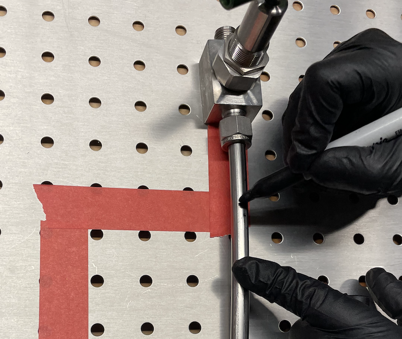
If you have a cut chunk of line that has bends in it, dry fit one end of the line into the fitting you are starting at. Make sure to be aligned along the tape in the correct location.
Using a marker, go along the line until you come to a 90 degree bend in the tape and mark a tic mark where the center of bend should be. Add an arrow along the tic mark in the direction of the bend. Adding arrows in the direction of the bend becomes helpful when you have a section with multiple bends in multiple directions.
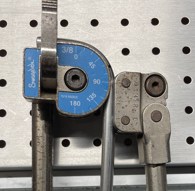
Using the 3/8” Swagelok Bending tool, insert the line into the groove, loosely clamp the tube latch so the tube will not fall but remain loose enough for movement. Make sure short handle sits above the line and is parallel with the line and long handle with the name plate is perpendicular to the line.
Adjust the roll support on the short handle so that the “0” tic mark on the roll support aligns vertically with the “0” tic mark on the name plate. For a 90 degree bend, align the tic mark on the line to the “L” tic mark on the roll support. Once set in place, fully latch the tube latch such that the line can no longer move.
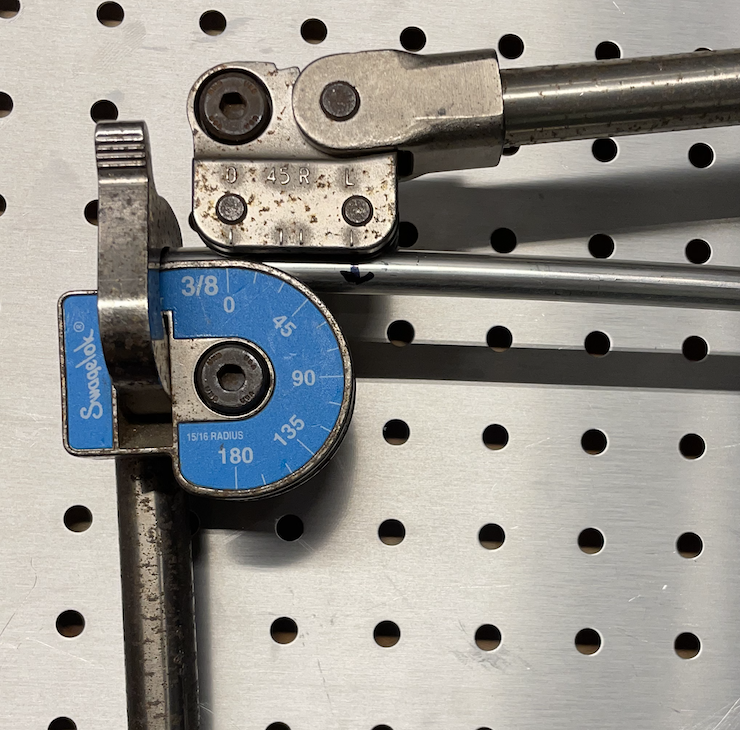
Once locked in place, with long handle perpendicular to the line and short handle parallel to the line, push down on the short handle to initiate the bend. For 90 degree bends, the final position of the “0” tic mark on the roll support should line up with the “90” tic mark on the name plate. Due to the slight level of elasticity, you can check and go a degree past since the line will bounce back slightly and may not result in a perfect 90 degree bend.
Dry fit the original end of line into the fitting to see how the bend aligns with the tape. If you have more bends to make, repeat the bending steps until you get to the next fitting. Check bends every time.
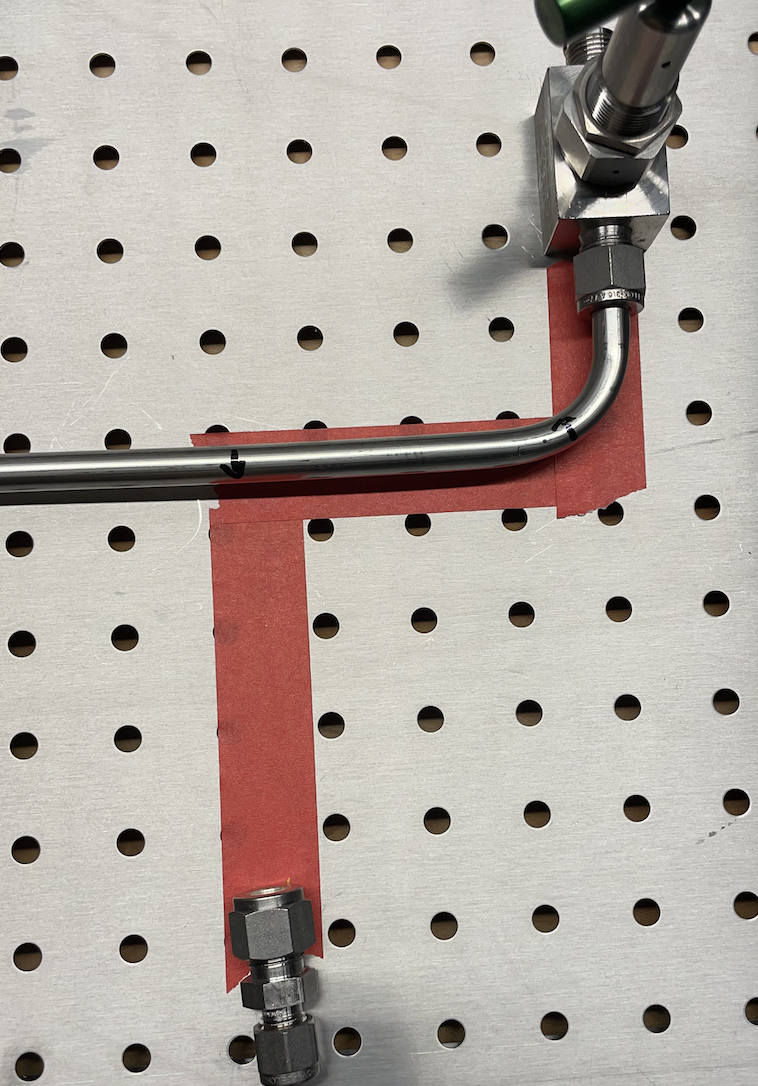
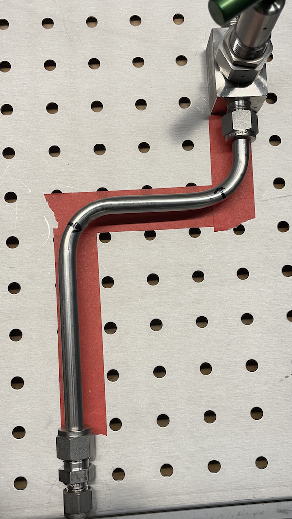
Once all bends are complete, dry fit the line into the original fitting that you worked off of. Check where the final alignment with the second fitting is. It should be slightly longer due to overestimating. Add a tic mark where it may need to be cut down to be in accordance to the shoulder of the second fitting. Refer back to Figure 6 and cutting directions to make the final cut so that all components are aligned in the correct position. Then go onto the next and final section for the swaging procedure. After cut, check to fit along the tape once more.
Swaging
When a piece of line is finalized and dry fit, take the Swagelok deburring tool and insert the point into each end of the line to deburr both sides as preparation for swaging.
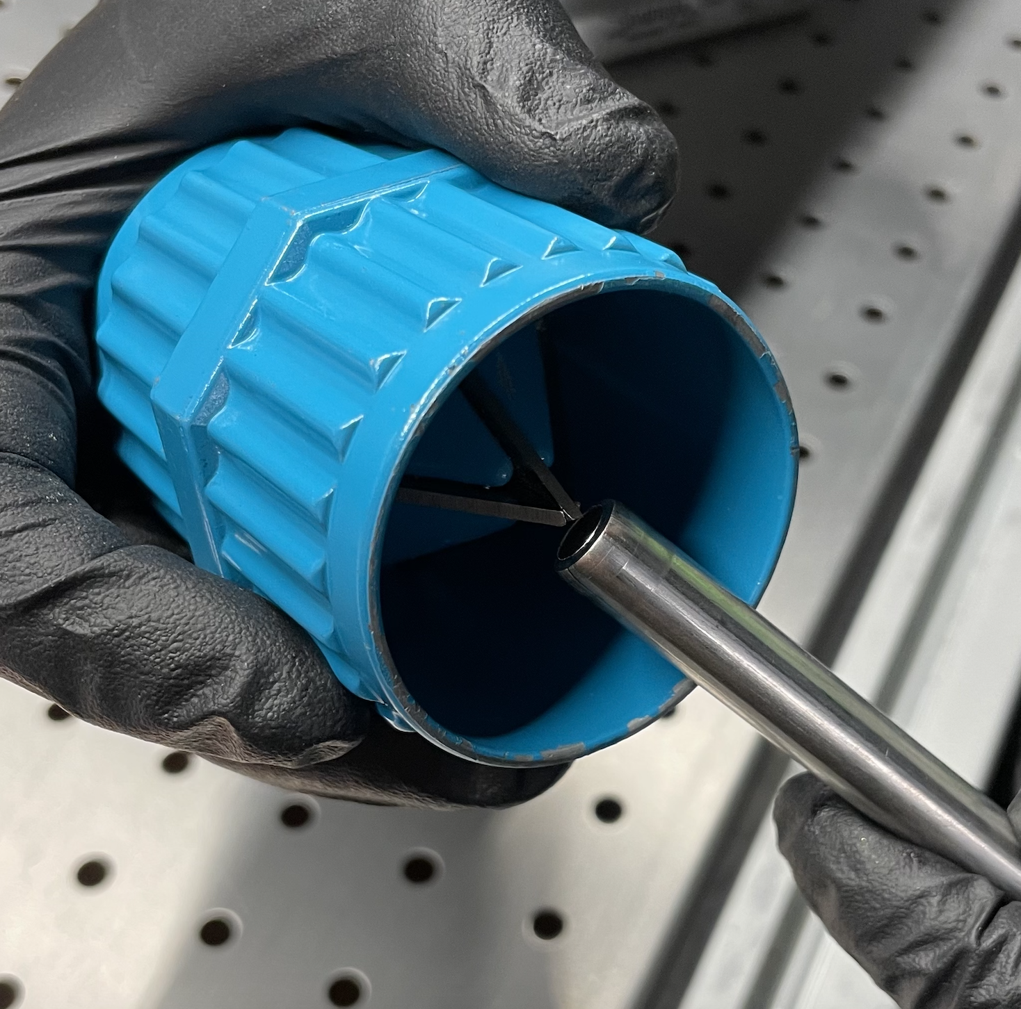
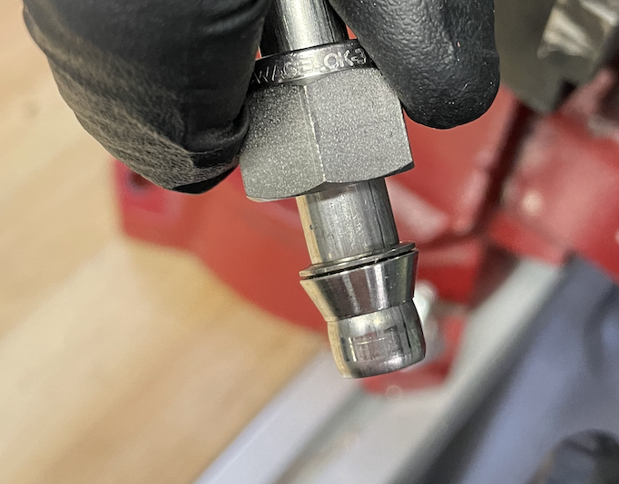
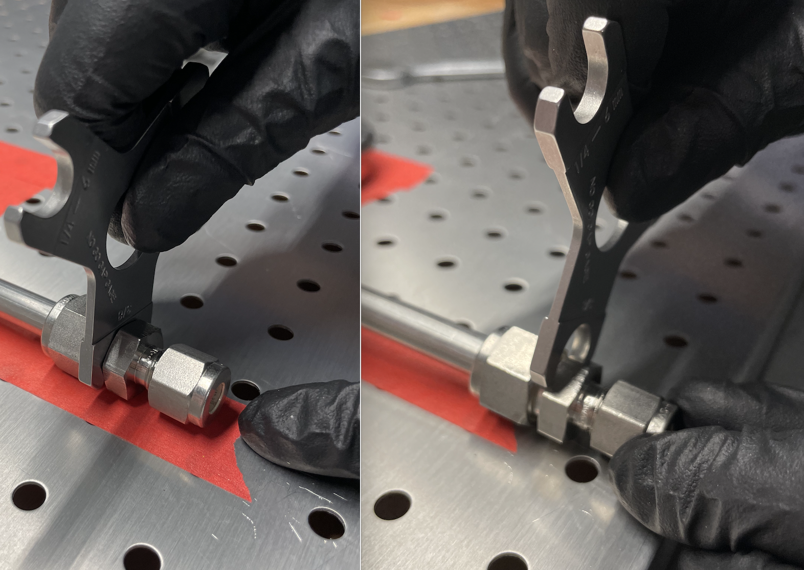
Take the desired fitting that you are swaging to and check by unscrewing the nut that is already there. Look inside the nut and there should be the back ferrule sitting against the back of the nut and the front ferrule sitting against the back ferrule such that the smaller diameter of the cone faces up and out of the nut. (Refer back to Figure 2 for proper orientation)
Just barely put the nut back on to the fitting. You do not want to screw the nut back on because that will prematurely lock the swage without having any line inserted and you will not be able to undo it to get the line through properly.
Put the desired fitting into a vice such that the nut sits face up so you can insert line into nut so that line is straight up and vertical. It is very important to make the sure line is sitting all the way in so that the opening face sits flush with the face inside the body bevel and that the line is not at an angle. If it is not all the way in or at an angle, it will not properly swage or form the proper seal. Before tightening the nut, with the line still in place, once more unscrew the nut while the line is inserted to make sure the rear and back ferrule are still in the correct orientation along the line.
Once all components are checked and in place, while holding the line straight vertically with one hand, using the other hand, screw the nut clockwise to be hand tight. Then take the wrench and insert onto the nut. Make note of what orientation you are starting with the wrench. The rule of thumb for swaging is you want to go one full revolution clockwise then ¼ revolution more. So if you start in the 6:00 position, do one full revolution to end in the 6:00 position first then go further to the 9:00 position.
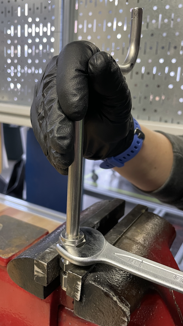
Once tightened, you should be able to do a small 90 degree counterclockwise and then the nut should be loose enough to untighten by hand. And you should be able to lift the line with the back and front ferrule firmly on the line. If you can not lift it straight out, very gently move the line side to side to get the line out. Do not apply torque to take out or you could risk altering the ferrule.
Once both sides of line are swaged, with their respective fitting, insert in the proper slot and tighten down. Start on the next piece and build outward one piece at a time by repeating the steps above from measuring to swaging.
It should be noted, that not every compression fitting is exactly the same. If you swage something on a fitting that you are not using for the specific piece of line, such as a dummy fitting, there is a chance it could fit slightly different for the actual fitting you are using even if it is the same size. It doesn’t mean it will not work, but it is a good way to mitigate complications by using the same fitting you will be using for that side of line in the manifold. Or use the appropriately sized pre-swaging tool.
Continually repeat this process from measuring, cutting, bending, and swaging until the manifold is complete. Depending on how complicated the system is and how many people are working on it, it can take two full working days or more to complete.
Once all components are swaged and locked into place, you can get a compression fitting gap inspection gauge. This tool allows you to access whether your compression fitting is on tight enough. Taking the appropriate side of the gauge. See if the prong of the tool is able to slip in-between the nut and shoulder of the fitting body. If it is able to slip in, it needs to be tightened further. If the tool is not able to slip in, then the compression fitting is tight enough.
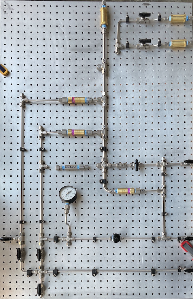
Once everything is checked and tightened, you can either remove all the tape that was laid down and labeled or leave it on. Taking all the tape off gives a cleaner look but if you tape it neatly, leaving the tape on gives a good color reference for future users who may not be as familiar with the system.
Lock down the line with fasteners that go through the pegboard. There is a large assortment of fasteners that can be used, including zip ties. After everything is securely fastened, it is now time to place the backboard of the manifold upright and fasten into its final resting spot adjacent to the system. Depending on the size, the manifolds can get heavy so having two to three people to carry and fasten it to its support structure is ideal.
You now have everything secure and in place with your vacuum chamber, K-bottles, manifold, and the room layout correct. Now what? It is now time to hook up the manifold to all the external components. This means hooking up line to the external supply lines in the room, the K bottles, manifold block, and the vacuum chamber. The exact same process from measuring, cutting, bending and swaging applies. The few differences are that you are doing it in a much more 3D setting since the line is not against a backboard. Here are some things to keep in mind:
- Start by doing one component at a time and try to reduce line cross overs as much as possible.
- Seeing it visually can be very difficult, especially when you have line going all around the room. Try to keep bends to a minimum and reduce pathway lengths as much as possible.
- When measuring, have one person holding the measuring tape at the fitting and try to visualize the pathway with all the bends.
- Draw what the general line will look like then add measurements. Give yourself at least 5″ or even more of excess line to work with depending on how complicated the bends are.
- After the line is cut, it may be useful to go ahead and swage one side of line so you can place your line on the fitting as a support while still holding it to determine where the next bend will be. For long lines of swage, you may need two people to hold the line upright in order to insure it is straight inside the body bevel.
- Otherwise, all the rules with measuring and bending still apply in the same way. Arrows become even more helpful in making the bends because you can have bends in all directions.
- Once you get to your final bend, complete it and dry fit the whole section of line from fitting to fitting. You may need to trim down the end that is not swaged because there should be some excess line due to overestimating the initial measurement. Then deburr and swage as usual.
End result is a simply structured, user- friendly, cryogenic plumbing manifold.
Testing the Manifold
Just as you would check a vacuum chamber for leaks, you also must do the same thing with your plumbing manifold. After the manifold is hooked up to the supply lines (helium and hydrogen in our case), vent stack, and the system itself (vacuum chamber), it is time to initiate vacuum pulldown. With hundreds of fitting interfaces, it is rare to have the system perfect the first time, although that is our goal. The most common issue that causes leaks is simply not tightening the fittings enough. Which luckily is a minor fix. To remedy this, tighten the nut further. Although we use the gage to measure if the nut is tight enough. Not every fitting is quite the same, thus you must tighten the nut further.
A mass spectrometer allows a system to maintain vacuum while simultaneously being able to sense when there are particles in a system. It provides a readout where instantaneous pressure and leak rate. You typically want the leak rate to be around 10E-8 mBar I/s. Ideal inlet pressure for operation is about 10E-7 mBar before you can begin to cool down a system. In general when you are doing leak checks, you slightly introduce helium around a fitting. If there is a leak, the helium atoms will travel through the manifold leak, through the manifold to the detector, and cause a spike in the leak rate which can jump up to 10E-3 mBar I/s and above.
It can take some time for the mass spectrometer to sense the helium as it travels through the system depending on how large it is. Therefore, this can be a very long and tedious process, so patience is key. Get just enough helium flow such that you can barely feel the cool flow on your lips from a flapper valve. The direct it via a needle towards a fitting to be tested. Helium rises so start at the top of your manifold and work your way down. Once you have a spike in the leak rate, you must wait for it to get back down to an acceptable rate in order to do another check which can take multiple minutes depending on how large the spike is.
Although the ideal operational rate for leaks is 10E-8 mBar I/s, it is possible to perform leak checks at a rate as high as 10E-3 mBar I/s. Sometimes, when you have a lot of leaks or even just one large one, until you figure out the location and fix it, that is as low as you can get. Because this process can be long and tedious, here are some tips and tricks to make it go as smoothly and systematically as possible:
- When checking across a manifold, work in sections. It is best to work from high to low. Helium travels upwards so can get sucked into other leaks if there are leaks above it. You want to resolve all the leaks at the highest points first then work your way down.
- Close the nearest set of valves to momentarily disregard the rest of the system. Then slowly spray a little helium to check if there is a spike. If there is no spike, you can mark with a physical identifier that the fittings for that section are good to go.
- If there is a leak, mark it so that you can tighten the compression or NPT fitting further. You MUST NOT tighten fittings while under vacuum so try to locate all your leaks then slowly introduce air back into the system until back to atmospheric pressure before you tighten a fitting. Tighten a fitting only in 1/8 turn increments at a time. This is the most common cause of leaks so will often fix the issue. Once you tighten further, check that valve once more. If that fixes it, open the next valve, and start leak checking each of the fittings along the way. Continue this process until you get through the entire manifold.
- Make sure you take your time with this process. Wait a moderate duration (sometimes upwards of 10 minutes) between each check to ensure that the reading is accurate. If readings are performed too close in duration, a recorded leak can come because of a previous check.
- If tightening a fitting does not resolve the leak, you can introduce air back into the system. After enough time has passed and when the system returns to atmospheric pressure, take off the fitting and check the ferrules. Could there be any bends, or could they be loose? If so, you may have to redo that section of line. could the NPT thread tape be improperly installed and not forming the proper seal? You may have to redo the thread tape.
- If the leaks are substantial to the point that you cannot get the leak rate down to an acceptable point, you can essentially do a reverse leak check. This can be done by dumping helium into the system and sniffing for leak origins, marking them with tape, and tighten accordingly.
The ideal result is when you can start cooling the system down. This is achieved at a leak rate of about 10E-8 mBar I/s and an inlet pressure of about 10E-7 mBar.
You can also use a stethoscope with the diaphragm removed to try to hear large leaks. Bubble testing also works, but why do that when you have a mass spec?
In the end, you should be able to pressurize your manifold with helium (e.g. 30 psig), close it off, and your manifold should maintain pressure over the weekend.
Gas manifolds get bumped, and things change. Our safety plans necessitate doing a leak check of manifolds at the start of every semester. This is also a great opportunity to train people in the operation of the experiment.
We hope you enjoyed this plumbing manifold guide! Be sure to send us your comments or suggestions.
Special thank you to Dr. Jacob Leachman, and masters students, Reece Adams and Mathew Hunt for their contributions in content and editing.